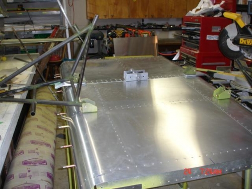
Brief Description: Completed landing gear instalation on bottom of ca
All hardware specified in drawings on cabin for the bottom landing gear brackets were to long and I replaced with one size down in length. I did not find any of the hardware in the kit for the brackets to cabin installation and had to purchase it. Using the 2 PF-170 I drilled though the bottom as per drawings and with bolts in place and center pin in for alignment. Drilled though cabin an bolted in place. Drilled 5/16 hole on the front pf each PF-176 and back side of both PF-168 and placed a bolt thought the landing gear leg on the front and PF-176 then drilling though the back hole of PF-168 and into the leg bushing I drilled though the other side of PF-168> Inserting a bolt though this hole I moved to the front and drilled though PF-176 and leg bushing to keep landing gear leg bolts in alignment. Then I completed the bolt holes on the other side. The landing gear legs tubing on top are of different lengths and will deed to be trimmed but all alignment and distances are right on. In building the center bracket you will have to clamp the two rubber peaces in place and drill through them. There is no measurements on the drawings for this placement. After talking to Don via email he said the rubber peaces are placed right between the end bolt through the cabin and the second one in on each side. After doing this I clamed in the center keeping the center pin in place for alignment and drilled though each rubber bumper.
Hardware - 8 x AN4-11A, 4 x AN3-11A with nuts and washers are for PF 161 and PF-176 to bottom. 8 x AN3-6A with washers and nuts for PF-168. 8 AN3-6A for PF-170. 2 AN5-24A for PF-170 though rubber bumpers.