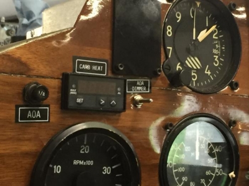
Brief Description: Finished Installing AOA Display on Instrument Pane
Mounted the ground wires from the AOA plug onto the ground buss in the center of the instrument panel. Slid the dimming pot into it's opening on the instrument panel and rotated it through 180 degrees. This left a mark on the back of the instrument where the tabs would go. Drilled a 3/32 inch hole on the mark at the 12 and 6 o’clock positions through the aluminum and not the veneer covering. Inserted the dimming pot into the hole in the instrument panel and seated it fully. Tighten the nut on the pot securing it firmly in the instrument panel. Turned on the power and then the avionics master switch and watched the AOA display go through its test cycle and then tested the dimming pot to observe it effect on the display. Everything tested correctly.
Placed a crimp terminal on the end of a segment of 18 gage red wire and covered it with a 5/8 inch length of heat-shrink tubing setting it in place with the heat gun. Connected the end of the wire to the avionics section of the terminal block in the center of the instrument panel. Routed this wire over to the circuit breaker area on the right side of the instrument panel and marked it at the opening for the ADS-B circuit breaker. Cut the wire at the mark and left it in place for the later installation of a crimped terminal on installation on the circuit breaker.
Created and applied labels for the AOA circuit breaker, dimmer and the ADS-B circuit breaker.