Brief Description: Installing Flight Instruments Into Pannel
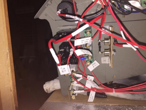
Went to the hardware store and purchased a box of 12 - 10 gage female terminal clips and a set of six #6 and 8 screws with nuts. Completed the ignition wiring from the diode to the circuit breakers by installing two clips and labels. Soldered the 12 gage wire to each of the diodes with a segment of tubing between the diodes. Connected the top diode to the emergency power switch with a red 12 gage wire labeled "EMGR PWR".
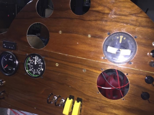
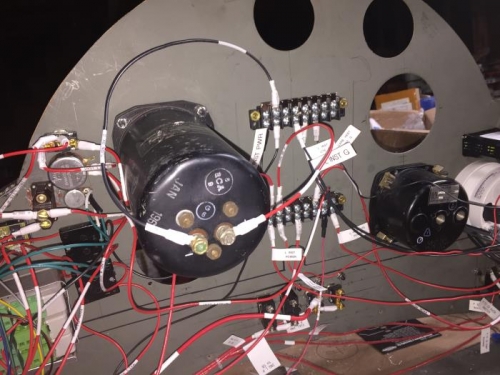
Mounted the airspeed indicator and drilled the mounting holes in the instrument panel. Installed four #6 screws to hold the airspeed indicator in place. Used the instrument template to pilot drill the mounting holes on the turn and bank indicator. Installed four #8 screws with lock nuts on the turn and bank indicator securing it to the instrument panel. Build up a 18 gage power wire labeled "TRN BNK P" connected from the "+" terminal of the indicator to the instrument power area of the terminal block. Build a 18 gage ground wire labeled "TRN BNK G" and connected it from the "-" terminal on the instrument to the ground terminal block.