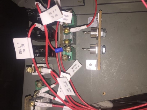
Brief Description: Mounting Emergency Power Diodes
Cut a 4 inch length of 1/8 by 1 inch fiber board. Drilled two 1/4 inch holes centered and 1/2 inch from the center of the board. Mounted each diode with a thin nut to the board. Installed a second thin nut on each diode. Cut two 5/8 by 1 inch segments from scrap 0.32 aluminum. Sanded the edges and rounded the corners. Bent each segment in half forming a 90 degree angle. Drilled a 1/8 inch hole in the center of each side of the angles. Mounted an angle to the ends of the diode board with a 1/8 inch pop rivet. Positioned the diode board on the back of the instrument panel next to the row of circuit breakers. Drilled a 3/32 inch pilot hole through the top bracket and the instrument panel. Drilled the pilot hole from the front of the instrument panel with a 1/8 drill and installed a pop rivet through the bracket. Positioned the board vertical and drilled the bottom bracket with a 3/32 inch pilot hole. Drilled the front of the instrument panel with a 1/8 inch drill and installed a pop rivet through the bracket. Measured a length of # 12 gage red wire from both diodes over to the top ignition circuit breaker. Removed 1 1/2 inch of insulation from one end of the #12 gage red wire and soldered the end strands together. Found that I didn't have any crimp connectors for 12 gage wire so set the wire aside for later completion.