Brief Description: Wiring Instrument Lights Left Side
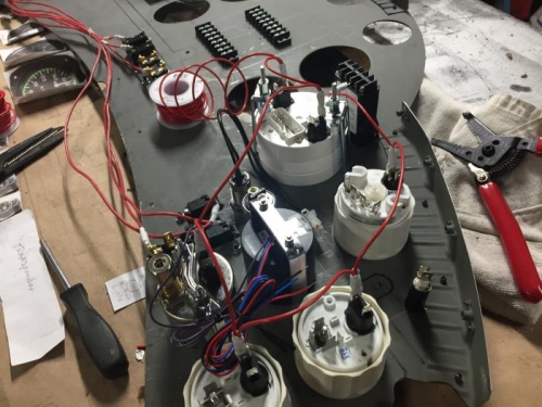
Crimped a "Y" connector to the end of a segment of 20 gage red wire and connected it to the third terminal of the carb head display. Attached the other end to another segment of 18 gage wire and soldered the ends together. Installed a female blade terminal at the junction of these two wires and crimped in place. Placed a 3/4 inch segment of shrink tubing over the terminal and heated it in place. Installed the blade terminal on the left blade of the instrument light on the EGT gage. Measured out a length of 18 gage red wire to the next instrument light. Wrapped the two wires together and soldered. Installed a female blade terminal and crimped in place. Placed a 3/4 inch segment of shrink tubing over the terminal and secured it with the heat gun. Continued adding segments of the power wiring until the oil pressure gage. At the oil pressure gage light three wires are soldered together and a terminal female blade is clamped in place. The purple wire from the CHT gage was added to the wires at the light terminal and controls the light level on the CHT gage. Measured off another segment of 18 gage red wire to reach the tac gage. Added the end of the spool to the terminal where it can be greater use. Wrapped the ends together and soldered together. Installed a blade terminal and plugged it into the TAC instrument light. End of day.