Brief Description: Installing Engine Instrurments in Panel
Installed a 1/8 inch pop rivet in the outside edge of the strobe shelf and drilled three lighting holes. Set it aside for later work.
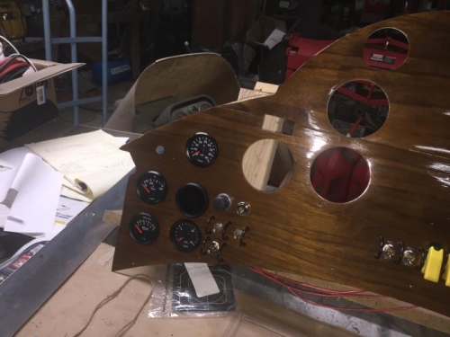
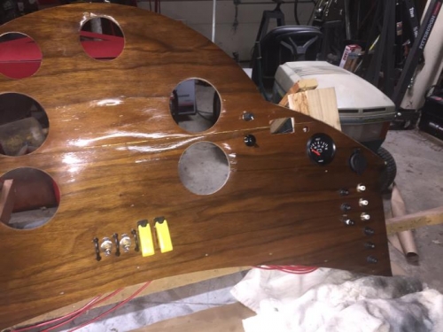
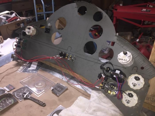
Installed a ninth 5 amp circuit breaker for power to the engine instruments. Installed the volt meter and connected the power lead from the instruments circuit breaker to the volt meter. Mounted the alternator warning light above and to the left of the volt meter. Installed the oil temp, oil pressure, fuel pressure, CRT and EGT gages into the left side of the panel. The red cover was installed on all instrument lights that came with the cover. Lots of wiring left for the next work day.