Brief Description: Construction of USB Power Supply and Instrument Pa
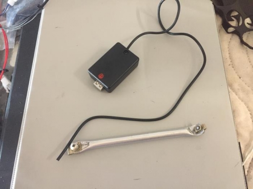
Flatten the end of a 3/8 inch aluminum tube and bent it at an angle of about 40 degrees. Laid the tube on the bottom lip of the instrument panel near the mixture control and marked the distance to the cross brace behind the instrument panel on the tube. Cut the tube at the mark and flatten that end about 5/8 inches back up the tube. Drilled a 9/64 inch hole in the bent end of the tube and slid a #6 clip nut onto the end. Drilled a 9/64 inch hole in the bottom lip of the instrument panel and secured the brace to the bottom lip. Positioned the brace up to the cross member and marked the position of the bracket on the flat area of the brace. Drilled a 11/64 inch hole in the brace and installed a #8 clip nut on the brace. Set the brace aside for later mounting.
Opened the small circuit box and used the dremel tool to remove one of the mounting post inside the box. Drilled a 5/32 inch hole in the end of the box next to the remaining mounting post. Carefully removed the USB power supply circuit board half way from its protective package and soldered the red and black wires to the plus and negative pads on the back of the circuit board. Again used the dremel tool to cut a slot in the end of the box where the mounting post had been removed. Place a mound of silicone on the bottom of the box and slid the USB circuit into the box and down onto the silicone. Cut a 5/8 inch square of heavy foam 3/8 inches thick to hold the circuit board in place inside the box. Installed the lid with a screw to keep all parts in place. Stripped 4 inches of cover from the two wires from the power supply. Removed a 1/4 inch of insulation from each of the wires and soldered their ends. Installed shrink tubing on each of the wires and then crimped a ring terminal on each. Set aside for later installation.
Drilled a pilot hole at the bottom of the ipad mount slightly on the left side. Used a step drilled to enlarge the hole to a 5/8 inch diameter. Installed a rubber grommet into the hole in the instrument panel. Routed t