Brief Description: Completed Installation of Flash Lube Kit
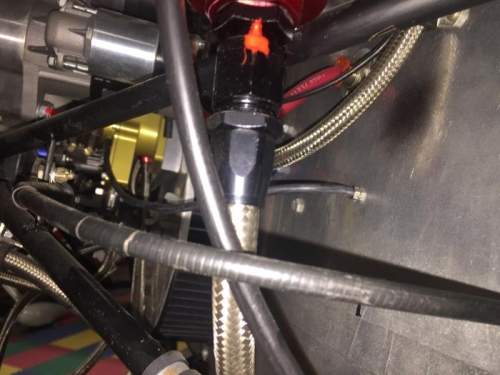
Measured the Flash Lube feed tube to the firewall. Cut the tube at the firewall. Marked the firewall at the point of desired penetration. Drilled a 3/16 inch hole through at the marked location. Installed the 1/8 inch barbed firewall fitting applying lock-tight to the treads. Pushed the Flash Lube feed tube onto the firewall barbed fitting. Drilled a 3.5 mm access hole on the carburetor throat. Inserted the provided self taping barb fitting and tighten it down on the carburetor. Put one end of the remaining feed tube on the firewall barb and measured off the tube to the carburetor fitting. Cut the feed tube to length and put it on the carburetor barb.
Installed the low level warning LED into the instrument panel just above the oil pressure warning light. Spliced the LED wires to the sensor wires from the Flash Lube container. Cut the green wire from the LED about 4 inches from the instrument panel. Ran a black ground to the green wire from the LED and completed the splice. Ran a red wire from the CHT instrument power and spliced it to the green wire to the low level sensor. Turned the master switch and observed that the low level LED glowed red. Filled the Flash Tube bottle and set the flow needle and lock it in place. Calibration of the flow rate will occur during the next engine run.