Brief Description: Installl CPI LCD and fit up the center stack close
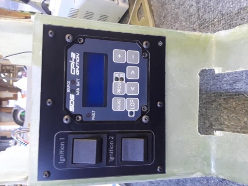
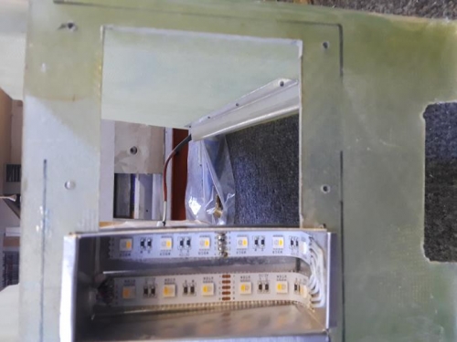
With all of the other components in place, I installed the CPI LCD in the center stack close out. The additional power switches for the dual system were installed into a new engraved switch plate with the same color adjustable back light as the balance of the switch plates. The big difference in the installation is I chose not to include connectors in the wires from the controller to the LCD head as a possible failure point. It made the installation a very close tolerance affair since the switches and LCD head must be able to slide back through the hole for maintenance.
A note about the switches required for the CPI system. The CPI left/right ignition check is accomplished by the traditional left/right start key switch. That does not power down the ignition controller. A left and right power switch are required to turn each board of the dual controller off. Without those switches the system would sense a power loss when the master was switched off and power up the boards with the auxiliary battery. The second board of the controller is powered from a direct battery buss that doesn’t turn off with the master, so a switch is necessary to power down. With both switches on, but no power from the ship (battery or VPX/main buss) , the auxiliary battery will power the system for 45 minutes.