Wired up the aileron trim tab. Began by drilling a 7/16" hole in the forward face of the aileron to push the 12 foot wire bundle through (protected by a teflon grommet). Next I soldered each of the leads coming off the Ray Allen trim servo to the individual wires in the wire bundle.
After soldering each wire, I covered it in heat shrink tubing to insulate it and give it added strength. On the other end of the wire bundle, I applied labels to the individual wires to assist in final assembly. I then tested the whole system by connecting the servo to the supplied trim switch and trim position indicator through the wire bundle and then applied power using a 14 volt power supply. I took a video of the trim tab motion from end to end.
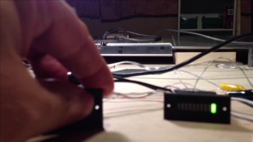
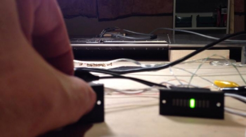
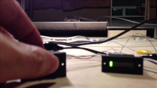
Below are three pictures from that video that show the switch (with my thumb on it), the LED indicator, and the aileron in the background (upside down to use the access panel on the bottom), and the trim tab at different deflections.
Trim tab full deflection "up" (since the aileron is upside down). Note the gauge indication.
Trim tab centered with the aileron, as is the indicator.
Trim tab full deflection "down" and the accompanying gauge indication.