Today I worked on the side attachment points for the fuselage. The specs are on the SLIDER drawing. (I had filed the slider and tail dragger drawings away.) I remember reading on a builder site that the scale drawings were on another page. (I also noticed a reference in the plans - but hidden.) USE drawing 24
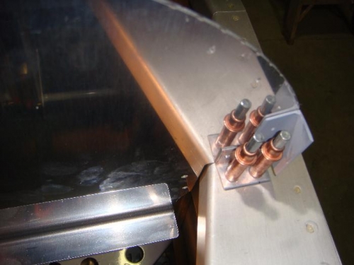
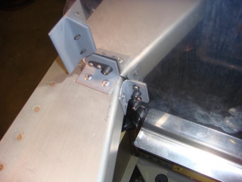
- I made sure the panel was straight across the cabin with a square. (Holding the panel up against the support angles. - Holding the 721C angle in place, I drilled the holes into the cabin frame. - I clecoed the 721C in place - Drilled through the hole in the frame to the angle - Disassembled and drilled the holes for the platenut - Countersunk for the 3-4 rivets (So panel will sit flush) - Primed the pieces and set them aside - Later I squeezed the rivets in place - Riveted the piece on
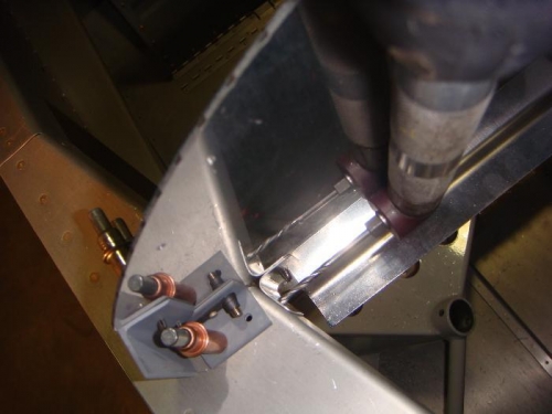
- Followed the basic same steps for the 721D (Scale drawing on Page 40) - I needed to use the 90 degree drill to drill the angle in place. - Countersunk holes for platenut rivets - Primed - Riveted into place