Brief Description: Molex connectors for fuse to wing junction
Decided to use 4 pin molex pins and 4 pin body for wing root area. The strobes and position light for each wing is a 3 wire shielded cable. I will use the 4th pin in body for the continuation of shield thru to the light.
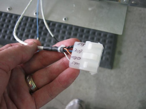
Strip wires and connected pins and installed in the molex body and labled each position. Ran out of female pins and will try radio shack for some otherwise another order to stein air for just a few pins. With the body installed, I used some shrink tube and zip ties as needed to clean up.
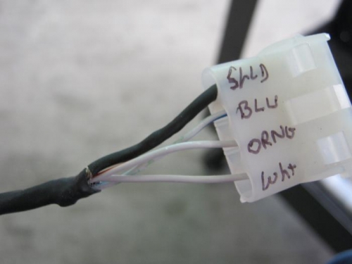
Point to note on shielded brade. On one side I soldered a 20 awg wire to the braide further back and then covered and then used a regular wire off that to go to the molex. On the other side I simply left the braid long and pulled wires out of a hole in braid at base and then twisted the shield braid and covered in shrink tube and conected the end of it to a molex. Dont think one way over the other is any better. I have some solderterminals that are great for this aplication because a pig tail inside the terminal to the braid and then simply use a heat gun to make clean connection, But mine were too small to fit so I used another method to get job done.
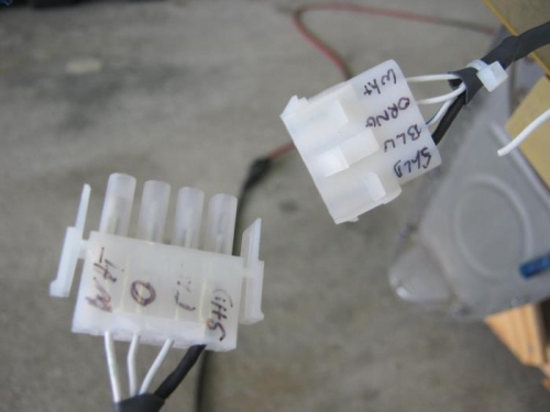
Did the same process on wing side ( the other half of the molex body. Decided to use the larger molex pins because radio shack didnt have anything. I simply folded the wire back over itself and the connector fit just fine with a solid crimp.
Wings should be ready for installing. Need to formulate a plan and figure out how to best position the plane in hangar.
I installed but splice terminals for the landing and taxi light and stallwarner wires. They are one time connectors but I have plenty of slack to do many times if need be. The molex idea isnt as much for quick disconnect as I dont plan on removing the wings over and over, but it makes it simple to get correct wires connected without fuss. I stll need to install the pins comming from the winf side.
Connector body done on left side fuse
See the shield wire covered in shrink? should work fine.
From the wing left and right. Have body halves reversed from left to right. No reason though