Brief Description: Access to the Auto Pilot Servos
There were two issues that had to be resolved after positioning the AP servos under the seat pan. First, the rear of the seat pan interfered with the pitch axis push rod. Second, access to the servos would be difficult after the seat pan and fuselage sides were riveted in place.
The answer to both problems was resolved by modifying the seat pan assembly. Clearance to the pitch axis push rod was created by shortening the seat pan, moving the rear of the pan forward by 2-1/4”. This moves the stiffening flange at the rear of the seat pan from immediately behind the flap control tube to immediately ahead of it. This raises the rear of the seat pan by about 5/8”, enough to clear the push rod by about ¼” at the highest point of its travel.
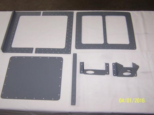
The access problem was resolved by adding an access panel to the seat pan. The center of the pan was cut out, and the pan was shortened by cutting the 2-1/4” from near the center of the pan, fore to aft. The access panel doubler was fabricated from 0.050” thick 6061-T6 and features a center web about ¾” wide. An inverted U-shaped cross brace stiffener is riveted to the underside of the center web to provide the strength needed to withstand the weight of a pilot using the seat as a transition step during entry and exit. The access cover will be attached with 8-32 washer head screws into PEM nuts in the doubler plate.
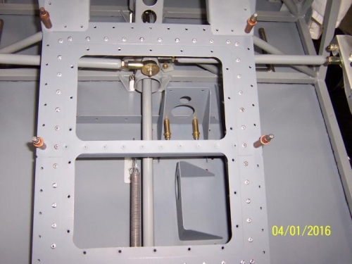
As you can see from the photos, there is relatively good access to the servos and their mounts, and access to the aileron push rod ends is also improved.
Modified Seat and Servo Mounts
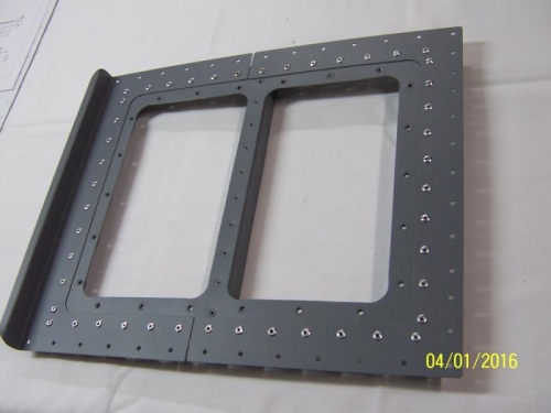
Modified Seat Pan w/o Access Cover
View of Servo Mounts and Controls Thru the Seat Pan