
|

|
|
|
Johns Web Site
|
Date: 11-18-2015
|
Number of Hours: 6.25
|
Manual Reference:
|
Brief Description: Ignition Tray Assembly
|
|
While waiting for the motivation to assemble the left fuel tank, I decided to design and fabricate the ignition system. The first item to be designed was the aluminum tray that will mount the two ignition coils, condenser, and ignition coil switcher. This tray is mounted directly behind the firewall on the right side. The tray design is relatively simple.
Five PEM nuts are pressed into the 0.050” thick aluminum tray to attach all of the components. Since PEM nuts do not have a locking feature, thread locker will be applied to the fasteners at final assembly.
Two aluminum angle clamp bars retain the two ignition coils in the tray.
While the tray is partially mounted to the center, fore/aft, fuselage tube, the design still allows the rudder pedal system to be moved rearward if needed in the future. I will probably remove the forward mounting tab because it is not necessary. The forward edge of the tray will be riveted to the firewall cross-tube, the rear mounting tab will be riveted to the fore/aft fuselage tube, and the right rear edge of the tray will be riveted to the diagonal fuselage tube.
After temporarily mounting the ignition tray assembly, a temporary acrylic firewall was fabricated and clecoed to the fuselage structure. This will be used for planning all of the firewall penetrations.
|
|
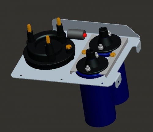
CAD Model of the Ignition Tray Assembly
|
|
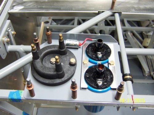
Resulting Ignition Tray Assembly
|
|
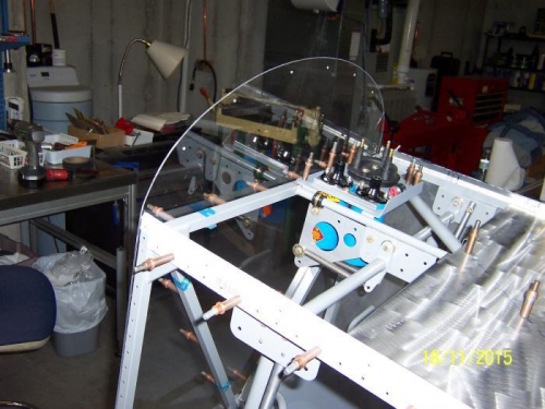
Acrylic Firewall for Penetration Planning
|
|
|
|
|
|
|
|
|
Copyright © 2001-2024 Matronics. All Rights Reserved.
|