
|

|
|
|
Johns Web Site
|
Date: 5-11-2015
|
Number of Hours: 5.00
|
Manual Reference:
|
Brief Description: Aft Fuselage Prep
|
|
The initial trial fit of former #1 led me to believe that considerable work was needed to get the former flanges to be parallel with the local top forward skin. However, after starting the process it proved to be much easier than I anticipated.
Throughout the process of assembling former #1 and the top forward skins, the front end of the aft fuselage was clamped with a flat aluminum bar to a dimension of 28” between the outside edges of the upper longerons.
With the #1 former halves clamped in approximate position, each of the rivet tabs was slightly bent with a slotted piece of wood until it aligned with a straight edge placed along the top skin and extending unto former #1. It took less time and manipulation of the rivet tabs than expected, yielding the desired results.
The rivet tabs at the top of former #1 were marked then sanded back to prevent overlapping of the former #2 rivet tabs.
To achieve the desired 1/16” extension of former #1 ahead of the top forward skins, I measured the distance from the pre-punched #40 holes in the top forward skins, and the edge of the skin, added 1/16”, yielding about 5/16”. Using an edge marker tool, a red line was made on the outer flange of the former as a target for the matched-drilling of the top forward skins to former #1. To align the red line on the former with the holes in the top forward skins, a piece of welding rod was bent with a hook on the business end, and a loop on the other to fit my finger. The hook end was slipped between the top forward skins and the former was then rotated 90-degrees to hook under the former flange, allowing me to manipulate the former so the red line was centered under the hole, while the hole was match-drilled. Due to the obtuse angle at the top of the former, the red line was ignored and the former was eyeballed to position, yielding a good looking result.
The upper lap joint between the two halves of former #1 was drilled and clecoed together.
|
|
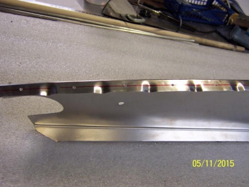
Former #1 Alignment Line
|
|
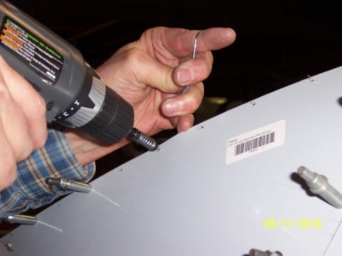
Wire Hook Used to Position The Alignment Line Before Match Drilling Former #1 to the Top Forward Skins
|
|
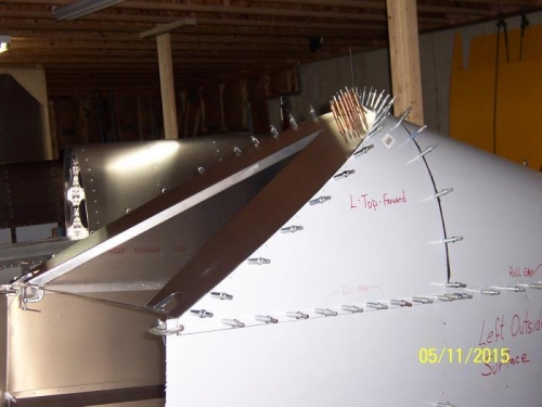
Ready for Dimpling with the DIENQ Dies
|
|
|
|
|
|
|
|
|
Copyright © 2001-2024 Matronics. All Rights Reserved.
|