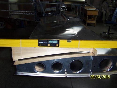
Today I fabricated a wood fixture to enable repeatable measurement of the wing incidence near the ends of both wings. The rear end of the fixture has a small step that catches the trailing edge of the upper wing skin, without interfering with the aileron hinge. This is the fore/aft reference point for repeatability. The forward end of the fixture rests on the leading edge skin at the forward edge of the front spar. A short cross piece is glued to the front edge of the fixture to keep the fixture from toppling. The digital level is held to the fixture with elastomeric retaining devices (rubber bands.) Since the fuel tanks are not in place, when checking the inboard positions, a 0.020” thick aluminum shim is placed between the spar and the front foot of the level fixture to simulate the thickness of the tank skin.
The only adjustment needed was to shim the right rear spar upward 0.055” to get both inboard ends of the wings at the same angle. There is a minor twist in the right wing, but it is within the BM specifications.
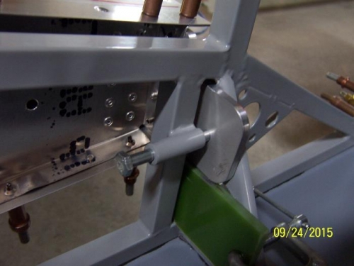
Before match drilling the rear spars to the fuselage pin guides, I measured the distance from both of the wing front, upper spar tips, to the upper surface of the intersection of the two horizontal stabilizer spar halves. Based on those measurements, the left wing rear spar was moved a few thousandths of an inch inboard to equalize the two measurements. With the rear spars clamped to the fuselage, the rear spars were drilled for their locking pins.