
|

|
|
|
Johns Web Site
|
Date: 4-2-2016
|
Number of Hours: 3.00
|
Manual Reference:
|
Brief Description: Engine Assembly - Rockers & Valve Adjustment
|
|
To prevent the crankshaft from turning while the safety shaft nut is torqued, the top cover was removed and a delrin rod inserted between a connecting rod and the case. The safety shaft nut was installed and torqued to 100 ft. lbs. The shaft was cross drilled for the cotter pin, then the cotter pin was installed, trimmed and locked in place.
My neighbor came over to help me move the engine from the stand, and mount it vertically on a small but robust aluminum table for the next phase of assembly.
The pushrods, rocker arms, grooved balls, retaining/adjusting nuts, and lock nuts were installed. During installation, cam lube was applied to the rocker arm ball seats, and the grooved balls.
Each of the rockers were adjusted using the process described in W.W.’s assembly video #2. When I finished the process, I noticed that one of the #4 cylinder hydraulic lifters was sitting slightly higher in the block, in its down position, than the others. To correct this, I carefully wedged a large screwdriver between the top of the lifter and the adjacent case, and applied a very small amount of pressure. The lifter moved to the correct position, and the engine was rotated through several revolutions to be sure the lifter correctly followed the cam. It functioned correctly, so the lifter was readjusted to accommodate the new neutral position. All of the rockers will be checked again before moving on the next part of the assembly process.
|
|
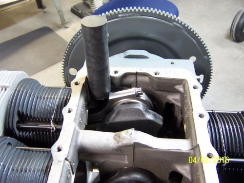
Delrin Rod Locking Crank for Prop Hub Nut Torquing
|
|
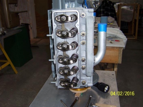
Right Head w/Valve Train Installed and Adjusted.
|
|
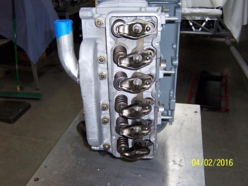
Left Head w/Valve Train Installed and Adjusted.
|
|
|
|
|
|
|
|
|
Copyright © 2001-2024 Matronics. All Rights Reserved.
|