
|

|
|
|
Johns Web Site
|
Date: 3-31-2016
|
Number of Hours: 6.00
|
Manual Reference:
|
Brief Description: Assembling the Right Cylinder Head
|
|
While waiting for the canopy interior paint to cure, I set up to finish the engine assembly. It took a while to figure out where I stored the components, but I finally found what I needed for today.
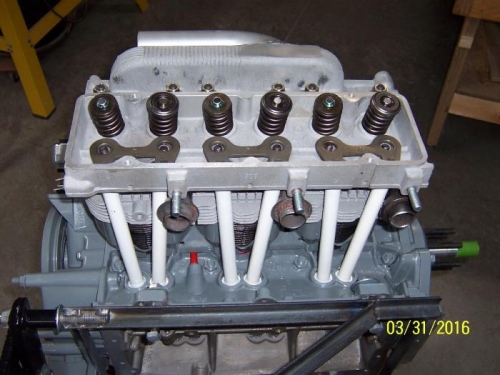
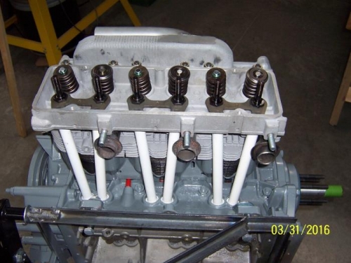
The valve hydraulic lifters were lubricated on the cam end with cam lube; the outside diameters were lubricated with a mixture of oil and STP, then they were slipped into their bores.
The lower cylinder baffles were positioned, then the head gaskets were positioned with the crowned side towards the cylinders. The cylinder head was slipped over the studs and seated against the head gaskets on the cylinders.
The push rod tube ends and O-rings were lubricated with White Lithium grease. They were positioned one at a time through the head, then the O-rings were installed on the ends. They were then positioned into their respective bores and pushed into position. The three push rod guides were set in position on the head.
Lithium grease was applied to the rocker arm stud O-rings, and they were seated on their bores. ARP Fastener Assembly Lube was applied to the upper stud threads, the face of the upper head nuts, and in the rocker arm threads and shoulder. White Lithium grease was also applied to the lower end of the rocker arm barrels.
The upper head bolts and washers, and the rocker arm studs were assembled finger tight.
A cardboard chart was cut and marked showing the correct head nut tightening sequence, and slid into position in the head. The upper nuts and rocker studs were torqued in sequence in five foot-pound increments, up to 28-foot pounds.
|
|
|
|
|
|
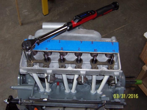
Torquing the Head Bolts and Rocker Studs
|
|
|
|
|
|
|
|
|
Copyright © 2001-2024 Matronics. All Rights Reserved.
|