
|

|
|
|
Johns Web Site
|
Date: 6-10-2016
|
Number of Hours: 4.00
|
Manual Reference:
|
Brief Description: Preliminary Engine Sensor Wiring
|
|
Today was spent planning and the initial routing of the EGT and CHT wiring. The EGT and CHT sensors come with approximately 24” long pigtails that are normally connected to the EIS wires somewhere behind the engine. This frequently leaves the connectors and excess wire wound up and clamped to one of the engine mount tubes.
In an effort to clean up the wire routing, preserve the ability to unplug these sensors when needed, and provide some protection for the interconnections, I decided to move the terminations into a protective enclosure mounted on the engine. After several false starts, I found that all of the sensor wires were long enough to reach a box mounted at the upper rear surface of the rear engine baffle. Some of the wires are longer than necessary, but the box is large enough that they can be coiled up inside the box. The box I chose was an Allied Electronics # 70148285, and costs $11.99 each. It is a die-cast aluminum box that is 4.545” long, 2.578” high, and 2.020” deep.
The sensor wires will come in the small ends of the box through grommets or plastic snap bushings, and the EIS wires will enter through a protected hole in the box cover. This will allow the cover to be removed and the connectors seperated without the need to pull the connector ends through a hole in the box.
The details are still being worked out, but it looks promising.
|
|
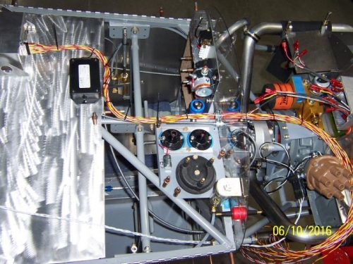
Top View From Avionics Tray to the Rear of the Engine
|
|
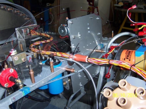
Looking from the Right Side of the Engine Through the Temporary Firewall
|
|
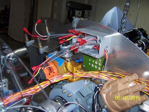
EGT and CHT Junction Box
|
|
|
|
|
|
|
|
|
Copyright © 2001-2024 Matronics. All Rights Reserved.
|