
|

|
|
|
Johns Web Site
|
Date: 8-23-2015
|
Number of Hours: 2.50
|
Manual Reference:
|
Brief Description: Plastigage Bearing Clearance Check
|
|
I recently received the last components needed to assemble the lower end of the Corvair Engine. Before assembly can actually begin, the main bearing clearance needs to be measured to be sure the variability of all the involved components stack up to the correct clearance range; for this engine the acceptable range is from 0.0007” to 0.0027”.
After a final cleanup of the case halves, and a careful alcohol cleaning of the crankshaft to remove the preservative oil, the bearing shells were placed in position in the case halves. Short pieces of green plastigage were laid in each of the four bearing shells, the crankshaft carefully set in place, the other case half was slipped into position, and the eight case assembly bolts were torque up to 50-ft.-lbs, in 10-ft-lb increments, using the torque pattern prescribed in the Corvair shop manual. Between torque increments, the case was struck firmly with a 2-pound dead-blow hammer, adjacent each bolt to be sure the case halves were seating together properly.
After achieving the specified torque on every bolt, the bolts were loosened and removed. The top case half was lifted off, then the crankshaft was carefully removed and set aside. The width of the Plastigage was checked against the printed gauge supplied with the plastigage, and the total range of all four was from 0.0018” to 0.002”, a very gratifying result.
|
|
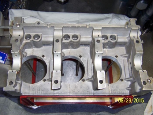
Case Half With Plastigage Ready to be Squeezed
|
|
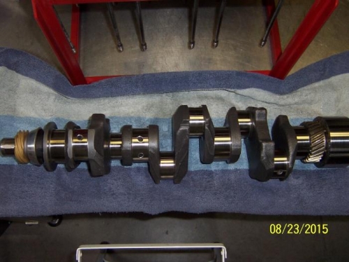
SPA Crank With Integral Fifth Bearing
|
|
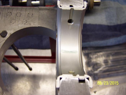
Thrust Bearing With Squeezed Plastigage
|
|
|
|
|
|
|
|
|
Copyright © 2001-2024 Matronics. All Rights Reserved.
|