In my other hobby of music composing you write based on influences and your own ideas.
Having flown the Airbus I have been influenced by the way the Airbus systems switches are integrated into simple system drawings engraved on the panel making them easy to understand. So I decided to have an electrics panel that utilises the switches on a diagram that represents the electrical system. Yes I know it's a simple VFR plane but this is my stamp on my aircraft and i think it's quite neat.
I also wanted to have the switches in front of me but not have them on the panel as removal would be more difficult. So in a rare moment of original thought I came up with the idea to screw the electrical panel to some unused map box angle attached to the aft cross brace and screw it to the main panel - so when the main panel is removed the electrical panel stays put. Bracing the main panel to the aft cross brace with the electrical panel also adds some rigidity to compensate for the large EFIS cut out.
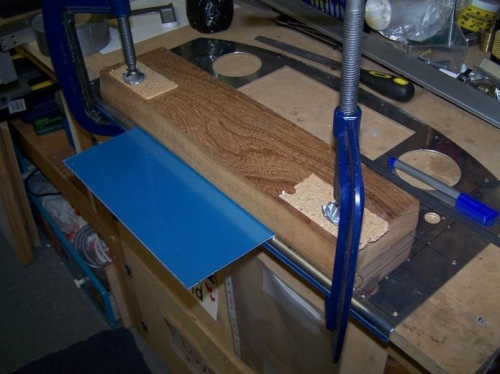
First I bent some 0.032 to 82 degrees usung the bottom of the main panel for the curve (main panel is angled 8 degrees forward).
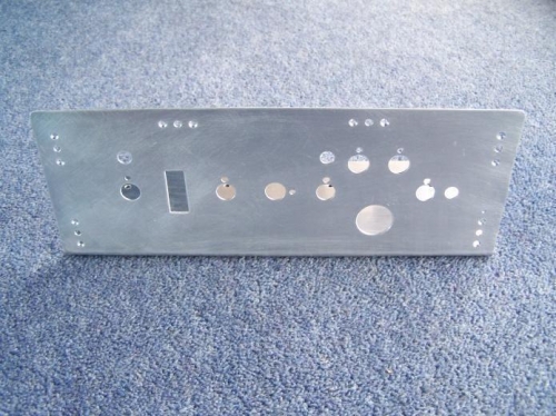
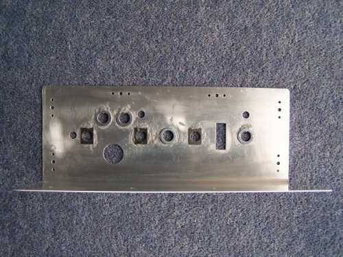
Then I marked and cut out all the holes that I had designed in Open Office Drawing software (CAD would be better if you are getting your panel engraved).
I also decided to bond the keyways with JB weld to fill the keyway hole as I originally intended to use decals over the panel.