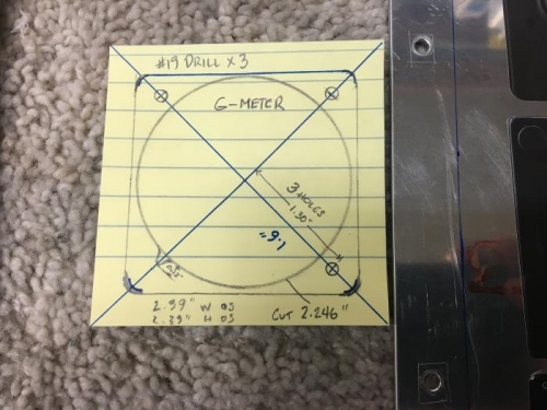
The difference between getting the cut dimension of an instrument and the specs is the cut dimension is one measurement whereas the specs are all of the measurements. The g-meter for instance is a 2.25” cut circle… but there are 3 mounting holes and a knob cut out that has to be accounted for. The time difference is that one takes 2-3 minutes and the other up to an hour. That being said, I got the g-meter specd out for the cut and also cut a paper sticker to go in the panel. In looking at the best place for it, I decided that the ELT switch should go over on the right side panel and the g-meter could go on the left above the fresh air vent.
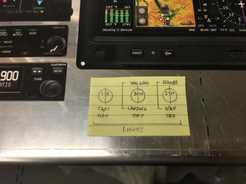
Next, I started pondering the which switches I would need and for that I consulted my electrical diagram and figured which switches I already have installed and which ones I need. In looking at the exterior lights I have Taxi, Landing, Wig-Wag (which is just flashing the landing lights for better recognition) Nav (position lights) and Strobes. Individually, that would be 5 (type 1-3) switches, or I can combine a few of these functions with the DPDT 2-10 type switches. The landing and wig-wag functions could be on the same 2-10 switch and could either be wired for OFF-Landing_ (OR) WIG-WAG or I could wire it to be activated as OFF-Landing only-Landing + Wig-Wag. Same with the Nav lights and strobes. So, I will look at the spacing of my other switches and see if I am low on space or not.