Brief Description: Roll bar Installation and Seat Backs Assembly
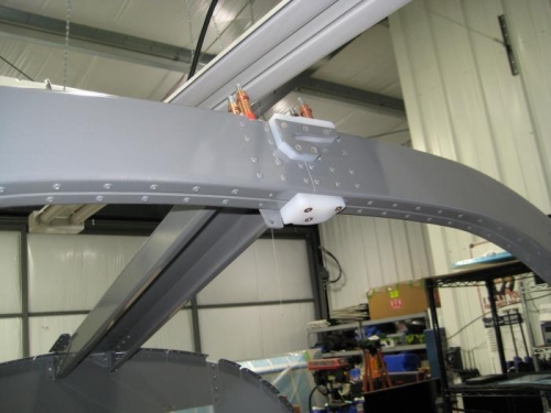
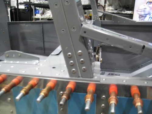
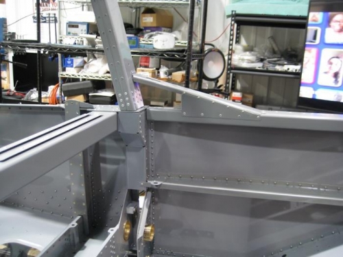
Completed step 15 page 24iS/U-02 that required the CR-3212-4-08 rivets Step 15: Riveted the F-1231E's and F-01231F-2 to the F-1231A-FL, -FR, -AL, & -AR per the call-outs in Figure 2, then riveted in place the C-01213A and C-01213B. Completed steps 4-5 page 24iS/U-04 Step 4: Clecoed, then riveted the Roll Bar Assembly to the F-1231D's per the call-outs in Figure 1. Step 5: Riveted the Roll Bar Support Assemblies to the Roll Bar Assembly and to the F-01234-L-1 & -R-1 as shown in Figure 1. Completed step 13 page 24iS/U-06 Step 13: Filled the two indicated holes in the F-01207C-R-1 with the rivets called out in Figure 4. Placed the manufactured head on the forward side.
Completed steps 1-3 page 25iS/U-02 Step 1: Removed the hatched area from lower end of the F-1237C-L and F-1237C-R as shown in Figure 1. Deburred the edges. Step 2: Separated the F-1237BD into the F-1237B and F-1237D by removing the hatched areas shown in Figure 2. Step 3: Separated the F-01437 into individual parts by removing the hatched areas Completed steps 1-10 page 25iS/U-03 for one set of seats Step 1: Removed the hinge pin from an AN257-P2 hinge. Retainws the hinge pin for use later in this section. Step 2: Fabricated the F-1237F from the two AN257-P2 hinge halves using the dimensions given in Figure 1. Step 3: Drilled #30 one locating hole in each half of the F-1237F using the dimensions given in Figure 1. Step 4: Drew a line on the 12 1/2 [317.5 mm] half of the F-1237F as shown in Figure 1. Step 5: Machine countersunk one side of the F-01437A for AN426AD3 rivets as indicated Figure 2. Step 6: Separatef the F-01437A into four individual parts by removing the hatched areas shown in Figure 2. Step 7: Clecoed the locating hole in the 13 1/2 [342.9 mm] half of the F-1237F to the F-01437, then aligned the parts parallel and firmly clamped them together. See Figure 3. Step 8: Match-Drilled #30 the holes in the F-01437 into the F-1237F. Clecoed each hole as it was drilled and continued to verify