
|

|
|
|
Johns Web Site
|
Date: 9-21-2020
|
Number of Hours: 5.00
|
Manual Reference: 21iS/U-06/07
|
Brief Description: Seat Rib Assemblies
|
|
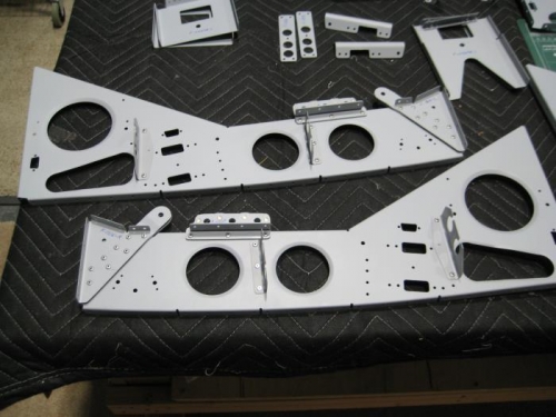
Completed steps 7 thru 11 page 21iS/U-06.
Step 7: Clecoed F-01299-L to #4. See Figure 6. Inspected for interference at oblong hole in rib #4 per the call-out. No interference found Repeated for #8. Repeated this Step for #1 and #5 using F- 01299-R instead. Step 8: Clecoed together F-00123A and F-00122 then machine countersunk #40 F-00123A per the call-out per Figure 7. Riveted together F-00123A and F-00122 per the call-out, then riveted this assembly to Rib #1. Repeaedt Step 8 for #5. Step 9: Machine countersunk #40 then riveted together F-00123B and F-00122 per the call-out, then riveted to #4 per Figure 6. Repeated for #8. Step 10: Clecoed together #5, F-01299-R & -L, and F-1216-R then final-drilled #30 the common eight 1/8 dia. holes per Figure 7. Riveted together #5, F-01299-R & -L, and F-1216-R. Repeated Step 10 for #1, and add F-12102A-L & F-12102B. Step 11: Clecoed then final-drilled #30 the eight 1/8 dia. holes in F-1216-L, F-01299-R, F-01299-L and #4 as shown in Figure 6, then rivetedthem together. Repeated Step 11 for #8 and added
F-12102A-R and F-12102B.
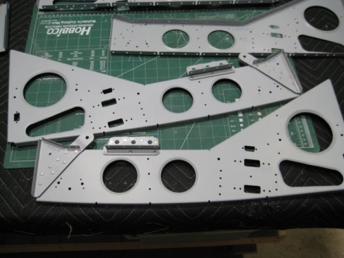
Completed steps 1 thru 9 page 21iS/U-07
Step 1: Dimpled #30 the hole in Ribs #4 and #5 fwd (sloped) flange per the call-out per Figure 1.
Step 2: Dimpled #30 the aft three holes in the middle flange of #4 and #5 per the call-outs.
Step 3: Dimpled #40 the middle rivet hole for a one-lug nutplate in the aft (sloped) flange of #4 and #5. Step 4: Riveted three nutplates to the fwd flange of #4 and #5 per the call-out. Step 5: Final-Drilled #19 the #30 nutplate screw holes in the fwd, middle and aft flanges of #4 and #5 per the call-out.
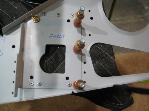
Step 6: Clecoed F-1269 to Rib #3 per Figure 2. Step 7: Match-Drilled #30 the three holes in #3 using F-1269 as a guide. Match-Drilled #12 the four holes in #3 using F-1269 as a guide. Marked and removed the hatched area. Deburred edges.
Step 8: Riveted F-1269 to #3 as shown except at the DO NOT RIVET locations called out. Step 9: Installed screw and hardware shown in Figure 2.
|
|
|
|
|
|
|
|
|
|
|
|
|
|
|
Copyright © 2001-2024 Matronics. All Rights Reserved.
|