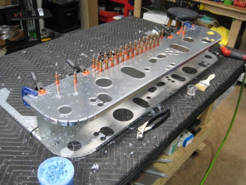
Completed the following steps page 20iS/u-02. Step 1: Machine countersunk #40 the nutplate rivet holes in the F-01204-1 bulkhead per Figure 1call-outs. Step 2: Installed nutplates on the F-01204-1 bulkhead per Figure 1 call-outs. Step 3: Machine countersunk #40 the nutplate rivet holes in F-01204F-L-1 & -R-1 per Figure 2 call-out. Step 4: Installed nutplates on F-01204F-L-1 & -R-1 per the call-out. Step 5: Final-Drilled #12 the two #30 holes in F-1204CL-R per the call-out in Figure 3. Set this assembly aside for use in the next section Step 6: Final-Drilled #12 the two #30 holes in the F-01204-1 Assembly per the call-out in Figure 4 Completed the following steps page 20iS/u-03. Step 1: Dimpled #30 the holes indicated in the tabs at the corners of F-01204D-1 as shown in Figure 1 detail view. Inserted any two AN4 bolts into the 1/4 inch holes in F-01204D-1 as shown in Figure 1 detail view. Rested the bottom surface of the F-01204-1 channel on the shanks of the two AN4 bolts per the call-out. Clamped F-01204D-1 to F-01204-1 channel with spring clamps as shown. Step 2: Placed F-01276-1 on the tabletop. Placed F-01204-1 over F-01276-1 and clecoed the bottom flanges of both bulkheads to the skin. Step 3: Temporarily loosened the spring clamps holding F-01204D-1 to F-01204-1 and allowed the parts to realign now that the F-01276-1 is clecoed in place. Re-tightened with C-clamps to securely hold the parts in alignment. Removed clecos from F-01276-1 and set aside.