Brief Description: Brake Cyckinders and Fuel System Start
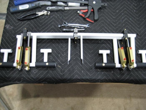
Completed step 7 page 28iS/U-03
Step 7: Attached the master cylinders to the WD-01206-1 Rudder Pedals and WD-1211-L & -R Brake Pedal Torque Tubes using the hardware called out in Figure 3.
Completed steps 1-6 page 27iS/U-02
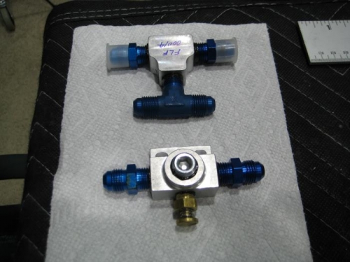
Step 1: Installed the fluid fittings into the FLF-00014 as shown in Figure 1. Clocked fittings in the orientation shown. Step 2: Installed the fluid fittings, plug, and CAV-110 into the FLF-00013 as shown in Figure 2.
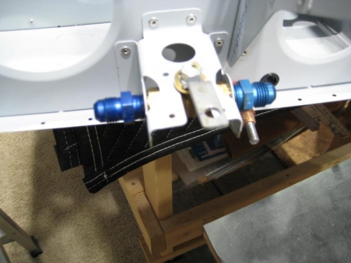
Step 3: Installed the fluid fittings, F-12129, and hardware onto the F-01201B-1 as shown in Figure 3. Applied sealant between the AN837 Union Bulkhead Fittings and the Firewall. Clocked fittings in the orientation shown. Step 4: Drilled 1/4 the Fuel Valve 4161089 handle per the dimensions given in Figure 4. Step 5: Installed the fluid fittings through the F-12108A and into the fuel valve as shown in Figure 5. Step 6: Riveted the F-12108B per the call-outs in Figure 5.