Brief Description: Continuing roll bar fabrication and assembly
Completed step 7 page 24iS/U-02
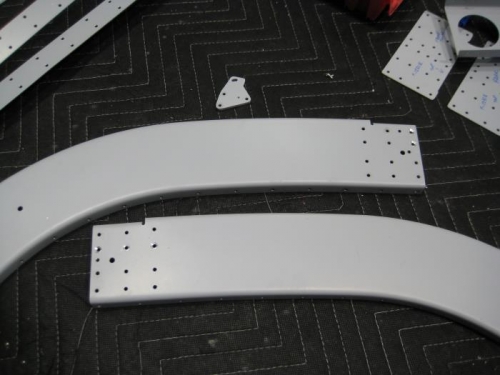
Step 7: Disassembled and deburred the roll bar parts.
Completed steps 10-13 page 24iS/U-02
Step 10: Machine countersunk the five holes on the forward face of the F-1231A-FL & -FR indicated in the detailed view of Figure 2. Step 11: Clecoed the F-01231F-2 to the F-1231A-AR and aft F-1231E. Match-Drilled #43 the switch mounting hole of the F-01231F-2 into the F-1231A-AR and F-1231E per the detail view in Figure 2. Step 12: Removed the F-01231F-2. Final-Drilled #30 the hole just created in the F-1231A-AR and F-1231E only. Step 13: Deburred the F-01231F-2 and tapped #4-40 the switch mounting hole in the F-01231F-2 only.