Completed step 2 page 23iS/U-07. Completed steps 1-8 page 23iS/U-08. Installed parts to perform step 11.
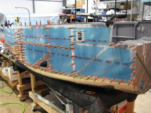
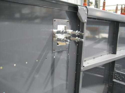
Step 2: Clecoed F-01270-L-1 & -R-1 (double check left and right), F-01270A-1 and F-1270D to the fuselage. Aligned the aft edge of F-01234-L-1 & -R-1 with the forward edge of F-01205B-L-1 & -R-1. Aligned the vertex of F-01255-L-1 & -R-1 with the upper edge of F-01270-L-1 & -R-1. Reference Page 23iS/U-02 Figure 2. Clamedp both parts together. Aligned the outboard edge of F-01205B-L-1 & -R-1 with the vertex of F-01255-L-1 & -R-1. Clamped both parts together
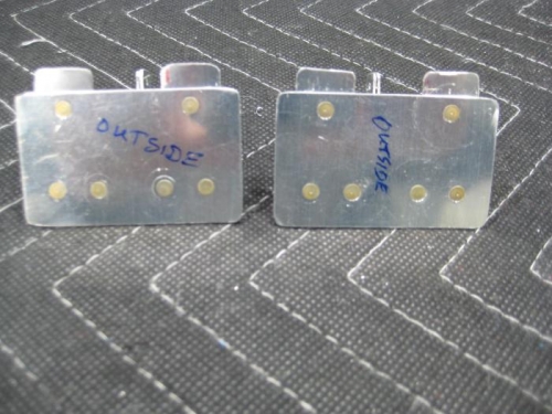
Step 1: Separates F-1086 into F-1086A and F-1086B parts as shown in Figure 1. Separates F-1087 into F-1087A and F-1087B parts as shown in Figure 2. Step 2: Clecoed together, final-drilled #40 all common holes then deburred F-1087A, F-1087B, F-1092 and F-1093 as shown in Figure 3. Step 3: Machine countersunk the holes in F-1093 for flush rivets on the outboard side of the aircraft. Step 4: Filed the edges of the slot smooth in F-1087A and F-1087B. Checked that an AN525-10R7 screw smoothly slides along the entire length of the slot. Step 5: Riveted the parts together to make the Vent Door Subassembly shown in Figure 3. Step 6: Machine countersunk one side of the VENT-00004 VENT KNOB for SCREW #4-40X3/8 SMS. Step 7: Inserted the tab portion of the Vent Door Subassembly fully into the slot of the VENT-00004 centered on the tab, orientws the previously countersunk hole towards the bottom of the vent door as shown in Figure 4. Step 8: Match Drilled #43 the Vent Door Subassembly using the hole in the VENT-00004.