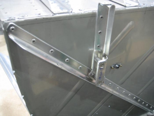
Step 8: Clecoed then riveted F-01217-L & -R to F-01272-1 using the hardware called out in Figure 2.
Completed steps 1-9 page 22iS/U-05
Step 1: Scuffed the bend radii around the aft side of the firewall perimeter. Also scuffed the top flange Scuffed the mating skins then cleaned all of the parts to provide good adhesion for a future fillet of sealant to be placed at their junction. Step 2: Clecoed together F-01201C-1, F-01217-L & -R, F-01272-1 as shown in Figure 1. Step 3: Riveted together F-01201C-1, F-01217-L & -R, and F-01272-1 using the hardware as shown in Figure 2. Riveted the seven nutplates to the bottom flange of F-01201C-1 and the fwd edge of F-01272-1 per the callouts in Figure 2.
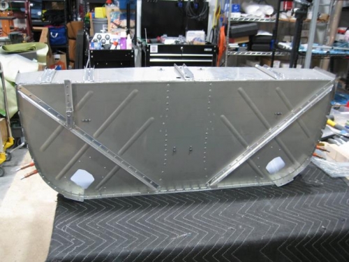
Step 4: Smeared a thin layer of fuel tank sealant on the top surface of the top flange of the F-01201C-1. then clecoed then riveted F-01201B-1 and all F-01257-1 per the Figure 2 call-outs. Step 5: Placed a fillet of sealant along the inside corner formed by the firewall and bottom skin in between the F-01217-L & -R per Figure 1. Step 6: Clecoed FF-01204D-L-1 & -R-1 and FF-00088A & B to F-01201C-1 per Figure 2 callouts.
Step 7: Machine countersunk the holes in FF-00089 for the flush screws called out in Figure 2. Step 8: Attached FF-00089 as shown in Figure 2. Inserted the called out screws, bushings, and hardware to check for fit. Final-Drilled #19 if/as required. Step 9: Riveted FF-00088A & B and FF-01204D-L-1 & -R-1 to F-01201C-1 per the call-outs.
Completed steps 1-5 page 22iS/U-06
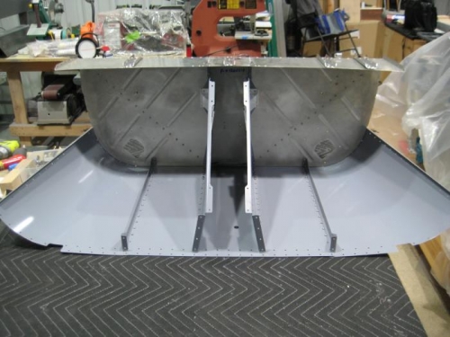
Step 1: Clecoed then riveted F-1271-L & -R as shown in Figure 1. Step 2: Bent the left side F-12130A and F-12130B by hand to match the curvature of the lower firewall flange then clecoed them in place at the #30 hole per Figure 2 detail view. Step 3: Final-Drilled #30 the #40 holes in F-12130A-L and F-12130B-L using the F-01201C-1 flange and F-1271-L as a guide. Removed and deburred. Step 4: Riveted F-12130A-L and F-12130B-L as shown in Figure 2 detail view. Step 5: Repeated Steps