Brief Description: Installing F-01203A-1 and F-01226-R-1 and L-1, Ste
Completed step 1 page 21iS/U-18. Step 1: Dimpled #30 the holes in the top flange of both inboard most F-01212-L-1 & -R-1 indicated in Figure 1.
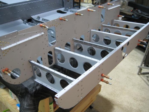
Completed steps 1-2 and 4-5 page 21iS/U-16 Step 1: Clecoed F-01203A-1 to the front flanges of each F-01215-L-1 & -R-1 and to the front flange of F-1253-L & -R. In order to align the holes in F-1253-L & -R with their corresponding holes in F-01203A-1 (the holes just below F-1203D-L & -R ), the F-1253-L & -R needed to be bent up slightly at the front of the seat floors. See Figure 1 call-out. Step 2: Riveted F-01203A-1 to the front flange of each F-01215-L-1 & -R-1 using the rivets called out in Figure 1 except where indicated. DID NOT rivet F-1253-L & -R at this time. Step 4: Riveted in place F-01226-R-1 using the called out rivets. Repeated this step for the left side of the fuselage. Step 5: Riveted the called out nutplates to F-01215-R-1 and F-01226-R-1 where indicated in Figure 3. Repeated this step for the left side of the fuselage.
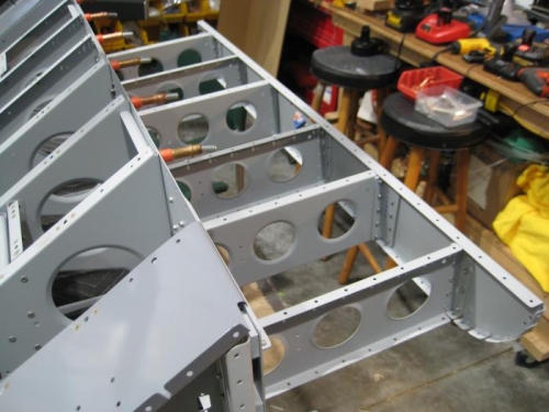
Completed step 5 page 21iS/U-17 Step 5: Clecoed then riveted the called out angles to the step ribs depicted in Figure 4. Hereafter refer to as Step Rib Assemblies.
Completed steps 2,4-8 page 21iS/U-18. Step 2: Dimpled #30 the bottom hole in the fwd flange of both outboard most Step Rib Assemblies and the two corresponding holes in F-01202F-1 where indicated.
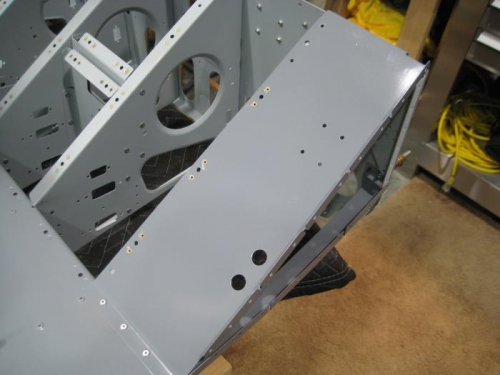
Step 4: Clecoed then riveted all Step Rib Assemblies and F-01212-L-1 & -R-1 to F-01203A-1 as shown in Figure 1. Step 5: Inseredt temporary bolts where indicated then clecoed F-01202F-1 to all Step Rib Assembly angles and F-01212-L-1 & -R-1. Step 6: Riveted F-01202F-1 ONLY to Step Rib Assembly angles. Step 7: Riveted F-01202F-1 to F-01212-L-1 & -R-1 and to the four Step Rib Assembly ribs with the exception of the four holes marked "CLECO, DO NOT RIVET." Final-Drilled #30 F-01202F-1 to F-01212-L-1 & -R-1 holes if/as req'd.
Step 8: Installed the called out snap bushings into the holes in the bulkheads where indicated in Figure 2 which depicted a rotated bottom v