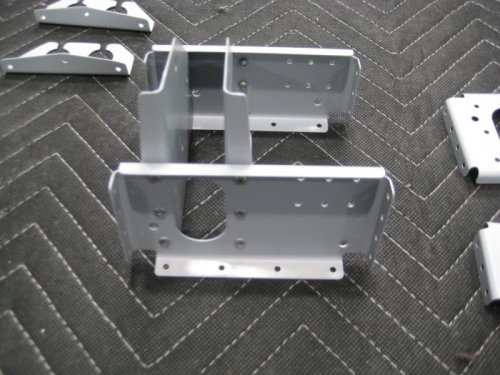
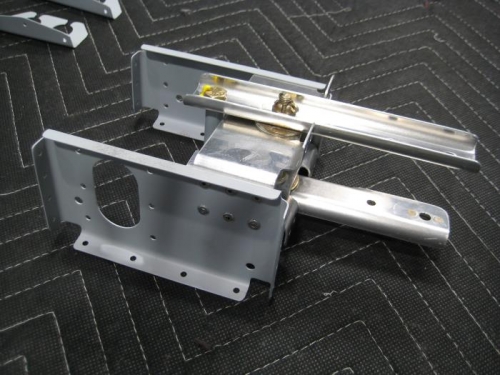
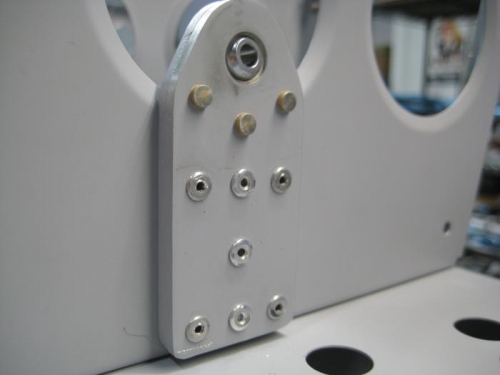
Brief Description: Pulley Bracket and Flaperon Mixer Arm
Completed steps 2 thru 12 page 21iS/U-05 Step 2: Riveted F-01206F-2 to F-1206J-L & -R . Step 3: Riveted F-01206F-2 to F-01206A-1. Instaledl the rivets from the aft side of F-01206A-1. Step 4: Riveted the Bearing Bracket Assemblies to F-1206G-L & -R and to F-1206J-L & -R using the rivets called out in Figure 1. Placed the flush, manufactured heads of the rivets in the Bearing Bracket Assemblies against the web of F-1206G-L & -R. Step 5: Riveted the nutplate from Step 1 to F-01206A-1 at this time. Step 6: Separated F-1250 by removing the hatched areas shown in Figure 2. Step 7: Rivetedt F-1250-L & -R to F-1220A and F-1220B using the rivets called out in Figure 3. Step 8: Separated F-01219-1 by removing the hatched area shown in Figure 4. Step 9 Riveted the two F-1218 to F-1220A and F-1220B using the rivets called out in Figure 5. Step 10: Machine countersunk #40 the nutplate attach rivet holes in F-01219A-1, then attach the called out nutplates. Applied grease to the hardware per call-out. Step 11: Bolted F-01219A-1 & B-1 and the shorter bushing to the two F-1218 using the hardware shown. Tightened the bolt enough to remove any slop or play but still allow freedom of rotation. Step 12: Bolted the second, longer bushing, between F-01219A-1 & B-1.