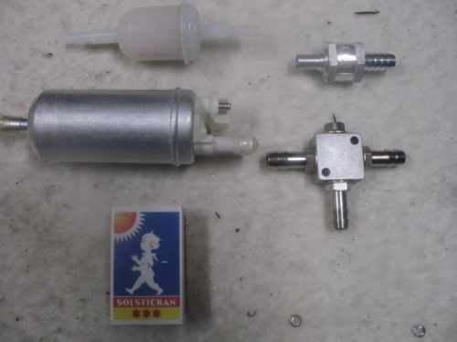
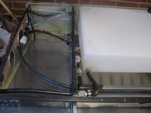
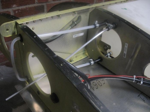
The fuel line is as follows: From the OUTER TANK (the extra tank) via a tube (1200 /6 mm) to a FILTER via a tube (480 /8mm) to an ELECTRIC PUMP (2 l/min) via a tube (55 /8 mm) to a ONE-WAY VALVE via tube (100/11 mm) to a 3-WAY CONNECTION. From the INNER TANK the fuel goes directly via a tube (350/11 mm) to the 3-WAY CONNECTION. The 3-way connection is directly linked to the right wing in- line connection of the 7 liter fuel reservoir. Installation of most pieces was fairly easy including the fuel return pipe and the visual fuel level gauge. Everything fitted well and nothing was missing. Grounding of the electric motor and the indicator lamp was done via rivetting the ground wires to the rib as recommended in the manual. All the operations was easy as everything was easy to access. I wonder how it will be when all of this need to be maintained through the limited access from the bottom and the inspection panel. I suppose that ICP delivered the electric pump to ensure a positiv fuel flow even when there is a wing low situation where the ouer wing tank may be well below the fuel reservoir and the engine carburator. Likewise, the one-way valve is to ensure that there is no fuel flow from the inner to the outer tank.
Filter, electric motor, one-way valve, 3-way connector