
|

|
|
|
Keiths Web Site
|
Date: 1-12-2010
|
Number of Hours: 5.00
|
Manual Reference:
|
Brief Description: P 31-06 Steps 2-4
|
|
A challenging day. Two tasks that others had found difficult, and I did too.
The first was to wire up and test the electrics that confirm whether the Fuselage Pins have been correctly inserted, and the wings are therefore "safe".
Magnets embedded within the pins are sensed by Reed Switches, or that's the theory. Any misalignment means that the switches do not allow current to flow, and the test (using the Autopilot Disconnect lamp) doesn't light up. The consensus seems to be to enlarge a "rivet" hole, that allows the Reed Switch to be located closer to the pin. The consensus is also to grind quite a lot of metal (1/8th inch or so) from the pin handle. I did both and managed to get the port pin to work correctly. The starboard pin was a bit more mischevious. Under test I could get the lamp to light, but it did not always extingush if the pin is not correctly inserted. We'll need to see how it performs for real, but may need tweaking a bit more. Significantly, the pins are position sensitive so won't work if they are interchanged. *Fix 'em good while you can. Otherwise turbulence will make the "pin unsafe" light up. Ask me how I know.*
Picture 1 shows the replacement latches riveted on. Pictures 2 and 3 show the port and starboard Reed Switches installed The starboard one has an earth strap attached. You can still see a cable tie attached to the Adel Clamp. I used this to hold it closed until I got the nut on. Interestingly, you cannot see the nuts, so I used the camera with a macro focus to look for me.
|
|
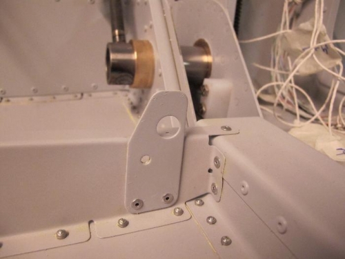
Replacement Pin Latch
|
|
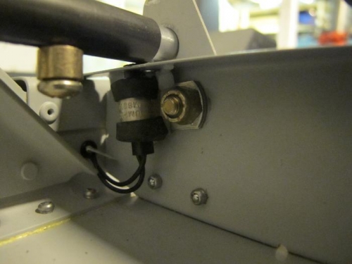
Port Reed Switch
|
|
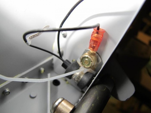
Starboard Reed Switch
|
|
|
|
|
|
|
|
|
Copyright © 2001-2024 Matronics. All Rights Reserved.
|