Brief Description: Assembling the Pitch Trim Servo
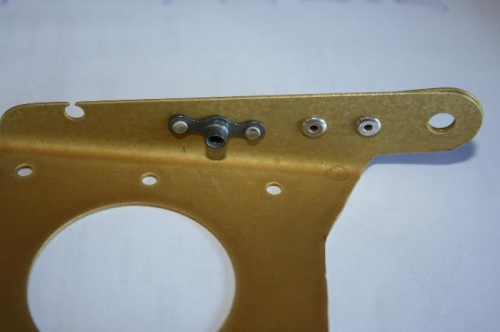
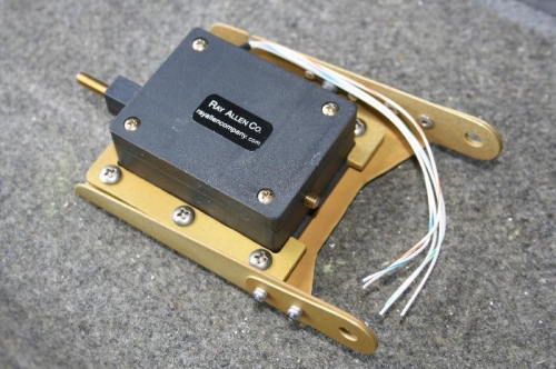
The Servo Tray just needs a nutplate (Picture 1) and two doublers (bottom right Picture 2) to be riveted on. Note the crescent shaped hole in one flange that looks like a mistake. Apparently it isn't. A small snap bushing goes in the hole to protect the bundle of small diameter wires.
The Ray Allen servo is held onto the tray with two U-shaped brackets and attached with 3 screws/bolts per side. See Picture 2.
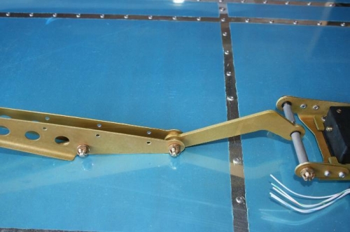
There's a fair amount of work on the Clevis Plates that I have not adequately illustrated with pictures. Picture 3 shows a trial fit of the various linkages between the clevis plates and the servo. At this point I have not finished work on the servo tray - in particular I have not put terminators on the thin wires, mostly because I'm chicken.
It took some time to prepare the two tubular spacers that fit on a long bolt in Picture 3 to locate the Link on the Sevo Tray. Apparently these need to be accurate to 1/32 inch, which isn't too easy with my eyesight and a steel rule. I do have a micrometer which measures metric stuff, so I have to use my mobile phone to do the conversion ;-)