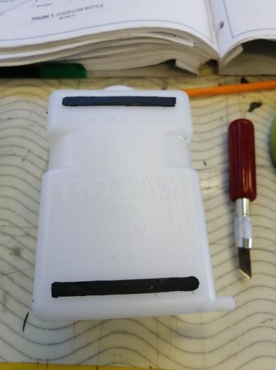
One layer of RTV was applied on the top and bottom of the aft side of the Overflow Bottle, afterwards a sheet of food paper was placed on the layers. The bottle was laid on the firewall to mold the RTV.
A Step drill was used to enlarge the hole of the cap to 3/8".
The bottle overflow cap was placed on the vise, fastening the connector between the jaws. A hammer was used to hit a 9/16" socket placed on the push nut to press it onto the connector and the cap.
A cutter was used to cut 40" lenght of PT-035 X 1/4 tube to create the FF-00094.
The FF-00094 was marked to 7/16" from one of its ends.
The marked end of the PT-035X1/4 tube was inserted into FLF-00007 until the mark was aligned with the end of it.
A cutter was used to cut 34" lengh of EA HOSE H175 to create the FF-01220-1.
Step 9 was started once cured the RTV (2 hours later application) and cut the excess. With the Bottle not place on its position was slipped one end of the FF-01220-1 (with clamp) Hose over the stem of the Bottle. A bit film of coolant was applied onto the end of the Hose like helpful to a better slip. The clamp was installed with helpful of a tweezer.
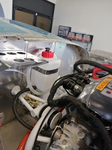
The Overflow Bottle was placed on final position.
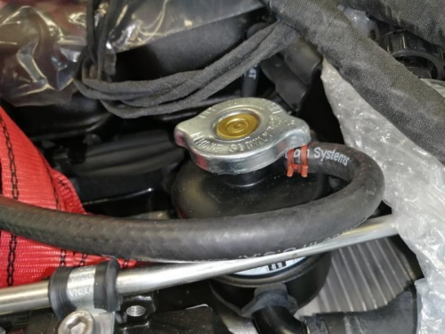
11: The free end the FF-01220-1 (with clamp) was routed and clamped to the barbed stem on the Expansion Tank.
02/28/20: 1Hr Steps 1, 9 and 10 were reworked since the RTV stuck to the firewall instead of the bottle. Rework Step 1, 9,10.. 1 hora.