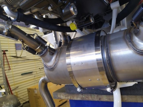
1. The EA LV-1 Heat Shields were installed on exhaust cylinders #1,#2 & #4 with clamps in the position shown
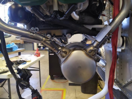
2. A light coating of high-temperature nickel base paste was applied to the inside surfaces of the four ball-joint receptacles on the Muffler Assembly.
3. The Muffler Assembly was attached to the four exhaust pipes using springs
Pliers were used to help with the installation of springs.
4. Cylinder #4 (EX-00024) was checked to see if there was a minimum 1/4" spacing between both springs and the EA LV-1. Otherwise it would have to be modified so that it would have that separation.
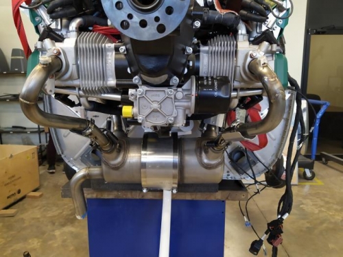
5. The nuts of each of the exhaust pipes were tightened enough and not completely , only to position them in the engine ports.
6. The Muffler Assembly was grasped and a fore-aft force was applied to it and ese moved from side to side, approximately one inch on each side of the center, so that the exhaust pipes would remain in their final stress position.
7. Finally a torque of 133 IN/LBS was applied to the 8 nuts of the exhaust pipes that were subsequently tightened.