
|

|
|
|
GA Aerospace’s Web Site
|
Date: 7-22-2019
|
Number of Hours: 7.33
|
Manual Reference:
|
Brief Description: 35iS/U-07, 37iS/U-15, 49iS-08, 42MiS/U-20, 53AiS/U
|
|
35iS/U-07
The dome plugs were installed
37iS/U-15
Since the oil door is already painted, the retaining washers were installed, to do so, a block of wood with a hole in it slightly smaller than the washer was used. The camlocs were positioned on top of it with the washer below and with a rubber mallet pressure was applied until the washer came into position.
38iS/U-18
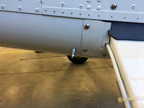
The overflow fuel line was finally fabricated. By cutting a 28in piece of ATO-035X1/4 and making two bends, one at 11" from the connector end and the otherone at 11 3/8" from the end of the first bend, then the fittings were installed and the tubing was flared.
The overflow line was hand-bent to go through the hole on the bottom of the fuselage, a 45 degree angle outboard is recommended, even though the manual doesn't specify, this way, the T-01236 will be much easier to install. After making the beveled end the fuel line and T-01236 were installed.
NOTE: By the time this page was performed a new revision still had not been released, the new dimensions were provided by Van's tech support which would make the job easier but still was a make-it-work thing.
49iS-08
F-12135 and CT-01205 were installed
42MiS/U-20
A unibit was used to expand the pilot hole on the left side cover, problem was that the center went offset and the hole was causing stress on FLF-00015-1. We worked on a new side cover and instead of using a unibit from the start, a 1/4 drill bit with a #20 pilot was used, after that the an unibit was used. The new side cover will have to be painted.
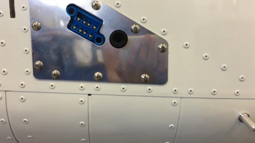
53AiS/U-02
A 1/2 was drilled into the bottom tailcone skin, a bit more forward than 2" to comply with the minimum distance indicated (Around 2 1/4") and alligned with the fourth rivet from the right stiffener to the left.
AV-00014 was installed and WH-00135 was connected to it and to ADS-B.
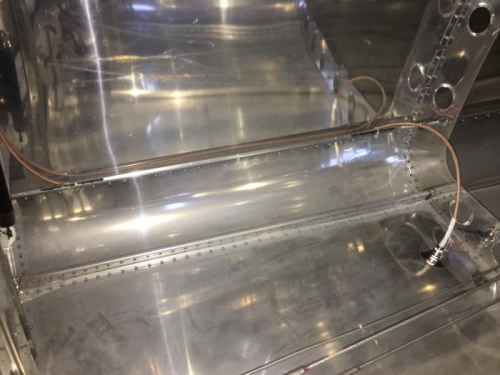
The connector was routed through the stiffener and cat-track was installed using RTV where the connector made contact with it, then it was tie-wrapped to the stiffener.
Steps 8-11
|
|
|
|
|
|
|
|
|
|
|
|
|
|
|
Copyright © 2001-2024 Matronics. All Rights Reserved.
|