Brief Description: Page 24iS / U-06 and 07 and 02 finished
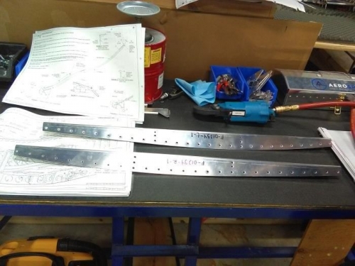
On this day the steps from 7 to 12 24iS / U-06 were carried out in which the pieces F-12111C and F-12111B were riveted to the pieces F-12111A-R & -L. Then the bottom nutplates to the F-12111A-L & -R were riveted in step 9 the taps of the fuel pump bracket assembly were inserted into the slots of the part f-12110 the assembly was secured with screws # 8. Finally, match drill was made on the nutplates screw holes in part F-01207C-L-1 using the assembly mud as a guide. in step 11 the deburring was carried out in the holes of both pieces and to finish in step 12 the nutplates K1000-08D with rivets AD426AD3-3.5 were installed. Also, steps 1 and 3 24iS / U-07 were carried out, in which the parts F-1207A, F-01207C-L-1 & -R-1 and F-01207D-L-1 & -R- were dimpling. 1. In step 3, 2 nutplates MS21055L08 and 2 MS21051L08 were drawn. Finally, steps 4 to 8 23iS / U-02 were carried out in which the part F-01234-L-1 was burned, in step 5, and match drill was performed in the drill holes indicated in the drawing (figure 1) to finish the part F-1255-L-1 was cut in the inboard edge.