I had to run some errands after work today so I got a late start. The first thing I did was to set the blank panel in place (it come uncut) and make the contour formed by the firwall and sub-panel onto the blank instument panel.
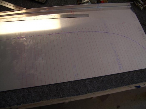
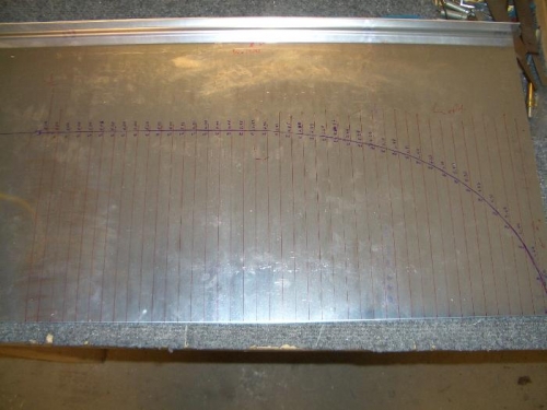
I am not planning to use this panel, so this exercise is just to validate my CAD design. I placed the blank panel upside-down across the longerons since they are my zero line for the panel measurements. I used a pen attached to some angle to mark the backside of the panel with the contour.
I tool the panel off the plane and mapped out the coordinates for the panel. It was tideious work, but worthwhile.
In the evening, I drew these measuement in CAD and compared them to my existing drawing. It was almost dead-on with a few very minor deviations. I am now confident that my CAD panel will fit correctly, however I am still leaving a little extra material in the design just in case.