Brief Description: Install Stall Warn, Begin Riveting Leading Edge
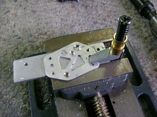
To assemble the stall warning I had to drill the mounting screw holes to #31 and countersink the mounting plate for #40 screws. The #31 holes were too small for my #30 countersink so I took some thick scrap that had some #40 holes in it and lined up the #31 holes over these. I used some other holes in the plate to match drill for clecos and then was able to use my #40 countersink to cut the #31 holes. I used a similar set up for the #19 screw hole and cut it with my #30 countersink. The rivet holes for the nutplates were counter sunk in the normal fashion. Once all the holes were prepped I primed the parts and assembled the stall warning per the OP-46 plans.
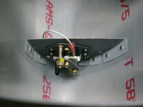
To make the ground wire I paid a visit to my buddy Kevin who had the proper avaition crimping tool. He taught me how to use it as we made the ground wire.
I used the gun and bucking bar to rivet in the VA-195 mounting bracket, then attached the stall warning sub-assembly and checked that we had good connections as the switch opened and closed.
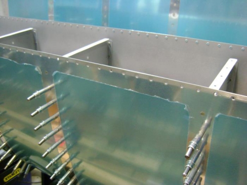
Last I installed the end rib and W-423 joint plate and cleco'd them in. Put the leading edge in the cradle and set the aft-most rivets with the squeezer.