
|

|
|
|
My RV-8 Build Log
|
Date: 3-14-2015
|
Number of Hours: 4.00
|
Manual Reference:
|
Brief Description: CAN Bus Construction
|
|
Building the Garmin CAN BUS required to connect the GSA 25, GEA 24, GDU 460, GTR 200, GSA 28 servos, and GMC 305. The CAN BUS is basically a two wire shielded circuit that interconnects all of the nodes (LRU - Line Replaceable Unit) on the bus. There is a HI and LO circuit, so the interconnect is a junction of two of the shielded wires spliced to a single wire so a pin can be crimped.
It's necessary to know how the LRUs will be located in the airframe to estimate the wire length, including the AP servos. Since the BUS must be terminated at both ends, I decided to terminate the CAN at each servo, one in the right wing at the aileron bell crank, the other in the tail at the elevator bell crank just past the baggage compartment.
Used solder sleeves to join all wires and performed a pull test, and continuity test for each node as construction was underway.
|
|
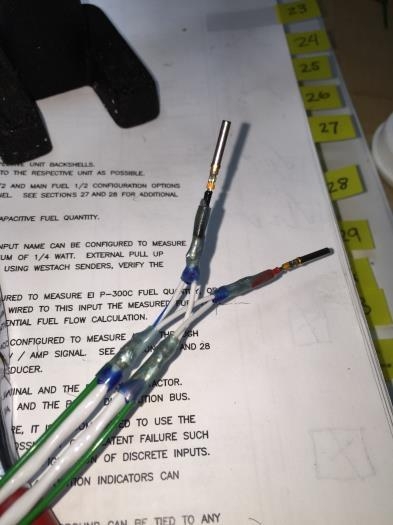
Can Bus Hi and LOW
|
|
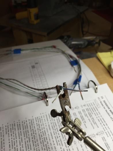
Constructing the CAN BUA
|
|
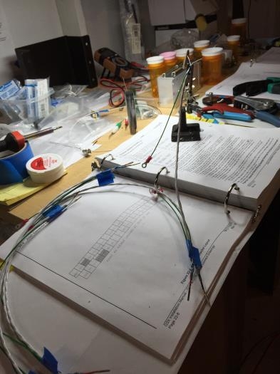
Building and Continuity Testing
|
|
|
|
|
|
|
|
|
Copyright © 2001-2024 Matronics. All Rights Reserved.
|