Brief Description: FWF Fuel Pump Vent and FW Cable Penetration
Install the Fuel Pump Vent Line:
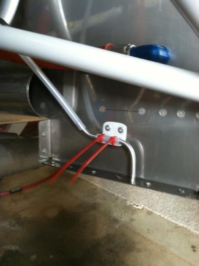
• Installed the brass fitting into the vent port of the Fuel Pump, downward orientation • Fabricated the vent line bracket per plans, located position on the FW per plans, drilled, primed and painted. • Fabricated the aluminum line which is attached to the bracket via cable ties per plan. • Attached vent line bracket to FW with blind rivets. • Fabricated plastic isolator from excess fuel vent line, attached to aluminum line. • Attached aluminum line with plastic isolator to the bracket using cable ties. • Attached the fuel pump vent line to aluminum line, used another cable tie to secure.
Final drilled the three FW penetration holes for the mixture, throttle and prop governor cables:
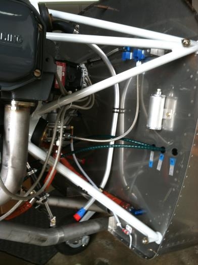
• Used step-drill bit to step up the size. • Installed specified snap bushing on control cable • Routed control cable through specified FW penetration hole • Inserted snap bushing on front side of FW • Installed specified snap bushing on aft side of FW, and installed in the previously installed snap bushing in the FW.
These penetrations will be finished with fire sleeve and stainless fittings.
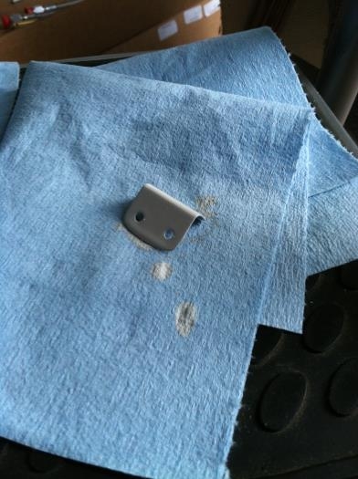
Fabricated Fuel Pump Vent Line Support Bracket
Fuel Pump Vent Line Installed using bracket and Soft Alum Line
Final Drilled size for Engine Control Cable FW, Routed Mixture and Throttle