Brief Description: Avionics ground bus (version 3)
I received the first prototype custom printed circuit (PC) board from ExpressPCB today. (Actually, I got four of them, which is their minimum order.) It looks good!
The PC board itself is the same width as the socket, so it'll fit inside my small enclosure just fine. My plan is that the PC board will not need any support at all after the socket and lead wires are soldered to it. It will just hang vertically from the bottom of the socket. This will greatly reduce the parts count and keep the unit as simple as possible. As long as the main lead wires are properly strain-relieved, this should be a very tough and foolproof ground bus.
I soldered a female socket to the board, did a continuity check, plugged in an empty male socket, and test-fit a few male pins. Everything checks out great. Final assembly of the unit will probably be early next week.
[UPDATE: This version of the Ground Bus design was updated later. Thje individual narrow traces were replaced by one large trace that encompassed all of the connector pins and the ground leads pads.]
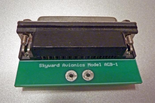
The female D-sub socket, mounted to the PC board.
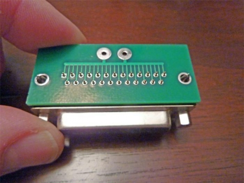
Bottom view, showing the grounding traces.
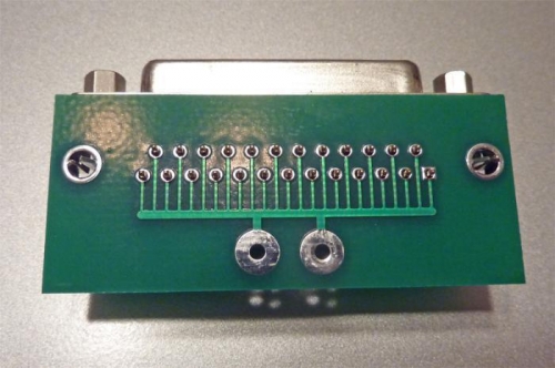
Another view. Two 14 AWG wires will be soldered to the pads at bottom.