
|

|
|
|
Buck's RV-8
|
Date: 11-18-2010
|
Number of Hours: 2.50
|
Manual Reference:
|
Brief Description: Avionics ground bus (version 2)
|
|
In the last few days, something began bothering me about Version 1 of my avionics ground bus. The 25-pin D-sub connector I'd used was the "solder cup" style, and the two 14-gauge wires I'd soldered to the back were not really mechanically secure before soldering. Mechanical security of a joint is one of the primary rules of soldering (especially for a connection that will be so critical, and subject to vibration, as this one). Honestly, it probably would have been fine, but I just can't compromise -- not with an avionics installation I will trust with my life someday.
So today I re-built the whole thing, this time using a different style of D-sub connector I got from a local electronics store. This one is a female 90-degree PC-board mount. Its long leads make it easy to curl the pins around the ground wires before soldering.
(UPDATE: Although this design might be adequate, I will be re-designing the avionics ground bus yet again. Version 3 will feature the D-sub socket soldered to a custom PC board inside the housing. The two 14 AWG ground wires will be soldered to the PC board. More in the next entry...)
|
|
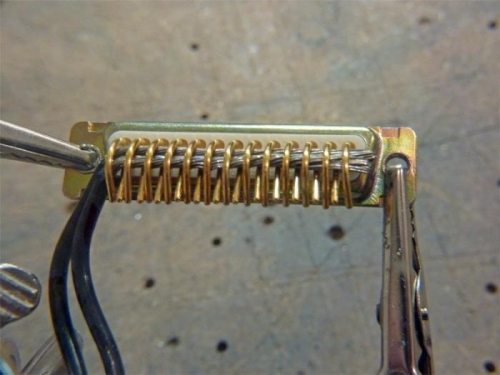
Avionics ground bus (v2), before soldering. Longs pins now give mechanical security to the connection.
|
|
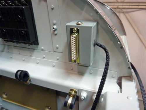
New avionics ground bus (v.2), installed. Ground lead goes to to the main firewall ground.
|
|
|
|
|
|
|
|
|
Copyright © 2001-2024 Matronics. All Rights Reserved.
|