Brief Description: Attachment Plates HS-012 and root ribs.
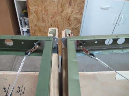
Pic 1. Rivet nose ribs and attach plates HS-012, front spar and root ribs.
NOTE: Orientation of the Attachment Plates HS-012. I found 3 places in the manual with various descriptions of the process for attaching the Right Bracket HS-012 as follows:
1) "The left HS is illustrated in this section.The right HS is assembled as a 'Mirror Image' of these illustrations." (Page5-2) 2) A manual drawing depicts the Right Stabilizer HS-012 upside down in the Circle with the caption: "This Way For the Right Stabilizer." The text states: "Note that the attachment plate HS-012 is mounted differently for the right horizontal stabilizer (this is the only difference between the two stabilizers." (pg 5-30) Note that this reference is made 12 pages after initial cleco construction of the left side. (I was simultaneously constructing left and right HS sections. 3) Later the manual states: "The right horizontal stabilizer will have the spar attachment bracket riveted upside down from this view." (Page 5-31) This reference is again made after initial construction.
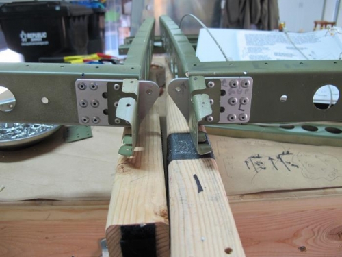
I found it difficult to hunt for and reconcile the various written descriptions (probably just old age) and drawings so I sent a picture of my "pre-built" HS to Lance who graciously provided the answer. The orientation in the first and second pictures here is correct. It would be helpful if Step 2. of the Manual: Assemble Front Spar to Spar Ribs included a a simple "as built" depiction of the correct orientation of the two HS-012 brackets when it describes construction of the left HS-012 at page 5-18 This would help old guys like me who dont like "Mirror Images" anymore
Pic 1. You are looking along Rib #1 for both L and R sections of the HS. The view here is from the trailing edge of the HS looking towards the leading edge of the HS. The left HS is on the left side of the photo and the right HS in on the right side of the photo. Each of the holes in the Attachment plates HS-012 is located at the top of the plate. . Pic 2 shows the view of the a