
|

|
|
|
Wendells RV-6A
|
Date: 12-19-2013
|
Number of Hours: 2.00
|
Manual Reference: Sensor Wires
|
Brief Description: FWF Sensor wiring continued.-2
|
|
Dynon uses a sensor wire to each P lead at the keyed switch with a 30K Ohm resistor in each line to measure RPM. Even though both mag P lead connections get wired, whichever one Dynon reads 1st gets used. So, more labels, more shrink wrap and more soldering in a "Z" shape to strengthen the wire at the resistor. Electrical work is my newest weakness so every time I get something done, its a big deal to me.
The starter switch is from a Cessna. The switch doesn't really locally ''ground'' anything. It internally connects the P leads to the shield connection at the proper times. The actual "grounding" is then done through the shield back to the mag where the shield itself is grounded to the mag. The switch connects the P lead internally to the common ground screw (the shielded wire connection). This happens when the key is 1)Off, 2)Start-it grounds right mag, and 3)When only one mag is selected, the other gets grounded. To ground the right mag during start (prevents kickback from early sparking), you add a jumper between the R and the R grd terminal next to it.
|
|
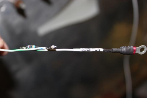
30K resistor soldered in place in a Z pattern for strength.
|
|
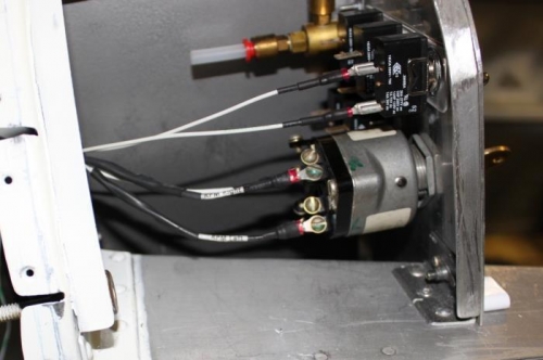
Labels-Shrinkwrap-mounted on switch. Add P leads, Shields, Bat connection now.
|
|
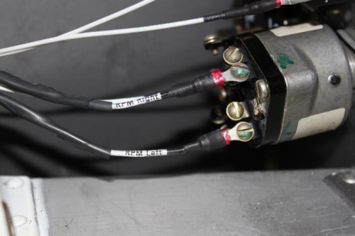
The switch gets both shields on same GRD screw. P lead-to-shield connection happens internally
|
|
|
|
|
|
|
|
|
Copyright © 2001-2024 Matronics. All Rights Reserved.
|