
|

|
|
|
Wendells RV-6A
|
Date: 12-20-2012
|
Number of Hours: 6.00
|
Manual Reference: Panel Layout 1
|
Brief Description: Instrument Panel Layout
|
|
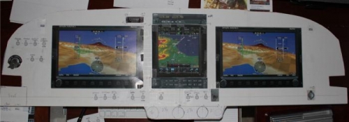
Used some poster board with 1/2 inch square shading lines and started laying out the instrument panel. Made a spreadsheet showing the four corners of square/rectangular stuff and central point/diameter of the round stuff. I'd sure like to find online templates to use with TurboCad somewhere but I just started with taping things where I thought I wanted them. This may be the final product for me. To the left of the pilot Dynon, I will have the ''early decision'' switches, like master, starter, avionics, co-pilot stick, alternate static, APRS. Below pilot Dynon is cluster with Defrost, Pitot Heat, Auto Pilot, spaces, then Boost Pump and Flaps. Under the center stack is Smoke, spaces, then Taxi/Landing, Strobe, Nav, Panel Dimmer. Over to the right of the Co Pilot Dynon is Aux Power Receptacle. Center stack top is SL40, then GTN750 (keeps the com freqs clustered together), then PMA 5000ex audio panel. ELT display above the Pilot Dynon. Dynon USB ports on top outside corner of each Display. 2.75 in. spacing between Throttle, Prop, Mixture centers and not decided if putting alt air and cabin heat there too. Have parking brake handle, and possible oil temp handle to locate too. Still enjoying coffee while thinking before I mark up the real panel.
|
|
|
|
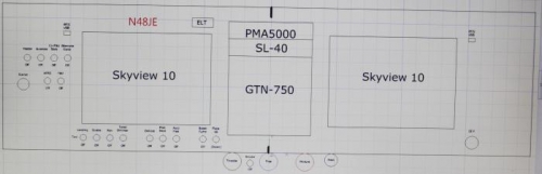
Maybe this layout
|
|
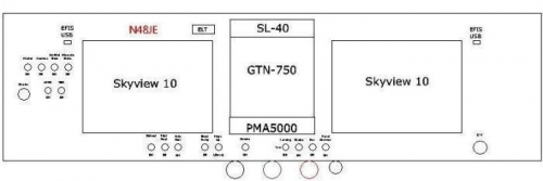
Maybe this layout. Using Turbocad
|
|
|
|
|
|
|
|
|
Copyright © 2001-2024 Matronics. All Rights Reserved.
|