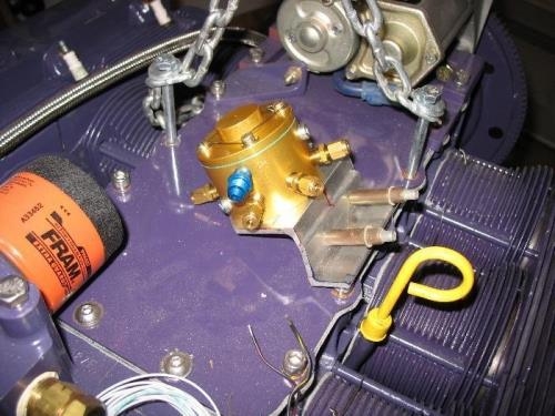
1) In this picture you will see a fitting of the Fuel Flow Divider (FFD) with its attachment brackets (still in rough form). The manifold will be as close to centered on the top of the engine block as is practical to keep fuel lines to the cylinders roughly uniform in length. The mount will pick up two of the bolts that hold the engine cover in place on the right side and is fabricated out of thick extrusion to minimize vibration due to flexing. The FFD has four holes threaded into its bottom for mounting but they are blind holes that do not go all the way through so there was some variability in getting the hole pattern on the mount correct. The screws are 10-24 thread fillister head (3/16†dia) so I drilled the holes oversized to make the alignment easier. Washers will help with the excess in hole diameter and the screws have holes in the heads to allow for safety wire. Interesting that the inlets/outlets on the FFM are not actually squared with the mounting holes and this leads to the fuel inlet line being offset to the right (fwd view). The fuel line from the FMU will be coming up on the right side anyway so I guess it all works out for the best. The one variation in the photo is that the assembly will be fitted one hole forward to stay away from brackets that add stiffnes to the aft cooling baffle. While I am at it I will fabricate a bracket to stiffen the oil dipstick tube mounting.