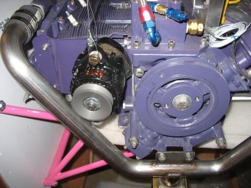
1) The design is roughly on paper so it is time to start fabrication. First step is to get the intake manifold pulley installed since it creates a potential interference that has to be watched. With the oil system line to the 5th bearing moved out of the way the alternator itself was suspended roughly in place to see how it looks overall. The pulley attached to the engine is a separate subject and it will go on the end of the Harmonic Balancer (HB). The HB is a pulley itself but would not get the belt far enough aft hence the need for an additional pulley and spacer. The dimensions have been checked for the lower bracket fabrication and that will not be finalized until that pulley is in place so the spacer length can be determined and the pulleys aligned. (Yes the engine is sitting sideways on the mount during this fabrication). Note that this is a 75 amp alternator, well beyond the typical 20 amp alternators used on the Corvair. There will still be a 20 amp John Deere alternator mounted to the front of the engine but it will be the backup to this main unit. The aircraft has a very robust electrical system with full interior and exterior lighting plus an electric heat system. That electric heater was developed years ago for the Eze family of aircraft. My philosophy is that engine compartment air belongs in the engine compartment, not the cabin.