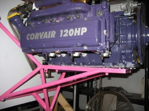
1) This weekend I have been looking at the installation of the major components for the fuel injection system on my Corvair engine. The critical part I needed was a stock WW Intake Manifold so I could see just where and how the components used in the Induction system would fit. The picture below shows the engine sitting lightly on the mount (no vibration isolator components yet and still attached to overhead chain hoist) with the Intake Manifold loosely in place. There is a tab on the lower part of the manifold that picks up two threaded studs that form the lower attachment for the rear accessory drive. For now it is just resting on the studs and I still need to take off the nuts/washers and mount it firmly in place so it cannot be knocked loose while fitting other components. The fit to the two intake pipes on the top of the engines does not look to be overly precise so I might have to use some force to get them properly aligned to fit my engine. You can just see the bottom of the mounting flange of the stainless steel exhaust manifold extending below the level of the engine oil pan. The induction system will have to clear the bracing for the nosegear mount so that limits the component placement to some degree.
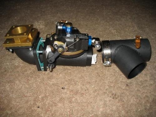
2) The components that I now have to deal with are seen in the second photo. First from the left / top is the gold colored adapter for tubing size made from machined aluminum. The standard Corvair flight engine Induction Manifold uses a smaller diameter than the FI system so this small adapter is required. The adapter has studs to attach to the elbow piece so only nuts / washers are needed there but the attachment to the main Induction Manifold will require the use of loose bolts (and a gasket that I do not have yet - a C-150 part). Next is the 90 degree elbow, a cast aluminum part with a black finish with paper gaskets on each end. It also has attached studs which extend forward and show one of the two gaskets used with this part. To the right of that is the most significant part of the system, the